
Steel framework enhancement composite pipe material bearing inserting and welding method

An enhanced composite and socket welding technology, applied in the direction of pipeline connection layout, pipe/pipe joints/pipe fittings, mechanical equipment, etc. Simple, manpower and equipment reduction, good pipe sealing performance

Inactive Publication Date: 2014-01-01
JIANGSU SHENSHI NEW MATERIAL TECH
View PDF0 Cites 5 Cited by
  • Summary
  • Abstract
  • Description
  • Claims
  • Application Information

AI Technical Summary

Problems solved by technology

The use of electrofusion sleeve connection welding has the following disadvantages: 1. Different molds need to be designed according to different pipe types and pressure levels, and the mold design and manufacturing costs are high; 2. Large equipment investment and energy consumption require additional injection molding machines, Solid plastic machine, wire winding machine and other equipment; 3. Because the electrofusion sleeve has no reinforcement layer, the pressure bearing capacity after welding is low; 4. Because the material used for the electrofusion sleeve is not the same as the material of the two pipes to be connected, there is an The plastic of the composite pipe itself has a potential safety hazard due to the rejection of the plastic and poor fusion, which leads to low quality and poor reliability of the hot-melt connection, and leakage occurs after the pipeline has been running for a period of time, which seriously affects the service life of the pipeline

Method used

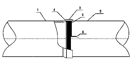
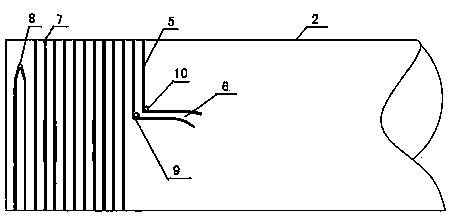

Image

  • Steel framework enhancement composite pipe material bearing inserting and welding method
  • Steel framework enhancement composite pipe material bearing inserting and welding method

Examples


Embodiment

[0031] Take welding DN250*12 pipe as an example.

[0032] 2. The present invention as figure 1 , figure 2 Shown, a kind of steel frame reinforced composite pipe socket welding method, the method comprises the following steps:

[0033] 1) Flaring:

[0034] ①A heater is used to heat the socket at one end of the first pipe, the heating current is 23.6A, and the melting time is 60 seconds;

[0035] ②When the reinforced layer steel skeleton reaches the set temperature, move the first pipe to the flaring machine, start the hydraulic device of the flaring machine to squeeze the socket section of the first pipe, and flaring to its inner diameter and the set The outer diameter of the second pipe material of the socket matches the size;

[0036] ③ After the flaring is completed, close the hydraulic device, cool for 10 minutes, and complete the flaring operation of the socket;

[0037] 2) Grooving

[0038] ①Return the rotating arm on the slotted thread distribution machine to the ...


PUM


Abstract

The invention discloses a steel framework enhancement composite pipe material bearing inserting and welding method, which comprises the following steps of (1) opening expansion: adopting a heater for heating a bearing opening, and starting an opening expansion machine for carrying out extrusion type opening expansion on the bearing opening section; (2) grooving: adopting a grooving wire distributing machine for realizing grooving on an inserting opening section, and the groove depth of a wire distributing groove is smaller than the thickness from the outer protecting layer to a steel formwork enhancement layer; (3) wire distribution; (4) insertion: inserting an inserting opening of the second pipe materials into the bearing opening of the first pipe material until the inserting opening is completely inserted into the bearing opening, and the concentricity of the two pipe materials maintains consistent; (5) fusion welding: respectively connecting two output power supply wires of an electric fusion welding machine onto binding terminals of electric heating wires, switching on a power supply, and carrying out segmented heating according to the pipe diameter parameters. The method provided by the invention has the advantages that the process design is reasonable, the method has good heat fusion performance and welding intensity, the pipe material connecting quality reliability, the pipe sealing performance and the pressure bearing capability are greatly improved, and the service life of the pipeline is obviously prolonged.

Description

technical field [0001] The invention relates to a steel skeleton reinforced composite pipe, in particular to a steel skeleton reinforced composite pipe socket welding method, which belongs to the technical field of pipe connection processing. Background technique [0002] In the prior art, the socket welding of the steel frame reinforced composite pipe is difficult because of the expansion of the socket. At present, the electrofusion sleeve type connection welding is generally used, and the sleeve with the electric heating wire is used as the socket. The two pipe ports to be connected are used as sockets, respectively inserted into the electric fusion sleeve, and connected to the power supply for welding. The use of electrofusion sleeve connection welding has the following disadvantages: 1. Different molds need to be designed according to different pipe types and pressure levels, and the mold design and manufacturing costs are high; 2. Large equipment investment and energy c...

Claims


Application Information

Patent Timeline
Patent Type & Authority Applications(China)
IPC IPC(8): F16L47/03
CPCF16L47/03
Inventor 刘海鹰仲宝付李强
Owner JIANGSU SHENSHI NEW MATERIAL TECH
Learn More