Near infrared household food detection device and method

A food detection and near-infrared technology, applied in measuring devices, material analysis by optical means, instruments, etc., can solve the problems of inaccurate detection results, inability to filter out, and poor detection results, and achieve good upgradeability and reliability. Scalability, improved filter effect, rich measurement results

Inactive Publication Date: 2014-01-01
WUXI X RES PROD DESIGN & RES
View PDF14 Cites 5 Cited by
  • Summary
  • Abstract
  • Description
  • Claims
  • Application Information

AI Technical Summary

Problems solved by technology

[0006] First, because the filter is set between the near-infrared light source and the Fresnel lens, it cannot filter out the influence of other wavelengths of stray light that may be received between the Fresnel lens and the sample cell, making the filtering effect imperfect;
[0007] Second, the wavelength of the filter is not disclosed in the invention patent, so it is understood that it can only transmit light of a specific wavelength or wavelength range. If the light of a specific wavelength is transmitted, it cannot be realized. Detection is carried out at other wavelengths; if the light of a specific wavelength range is transmitted, the light of each wavelength in this range is mixed together, and the detection effect is not good;
[0008] Third, the sample cell used in this invention belongs to the container. When the near-infrared light passes through the container wall, it will inevitably be affected by the optical properties of the container wall material or components, and this effect will be transmitted to the test results, making the test results inaccurate. ;

Method used


Image

  • Near infrared household food detection device and method
  • Near infrared household food detection device and method
  • Near infrared household food detection device and method

Examples


specific Embodiment 1

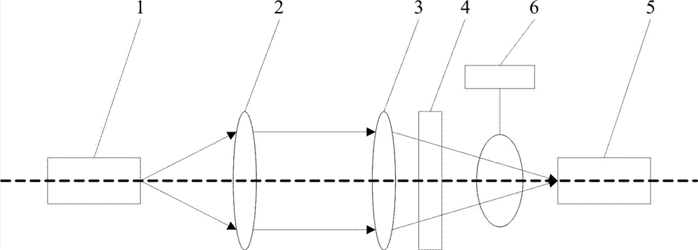
[0029] The structural schematic diagram of the near-infrared household food detection device of this embodiment is as follows: figure 1 As shown, the device is provided with a near-infrared light-emitting diode 1, a collimating objective lens 2, a focusing lens 3, an optical filter 4 and a detector 5 in sequence along the optical axis; the near-infrared light emitted by the near-infrared light-emitting diode 1 passes through the collimating objective lens 2 Parallel emission after collimation, then converge on the detector 5 through the focusing lens 3; the near-infrared light-emitting diode 1 is arranged at the focus position of the collimating objective lens 2, and the intermediate position between the optical filter 4 and the detector 5 On the top, there is a sample rack 6; the detector 5 is provided with a USB interface connected to a computer, and is connected to the computer through a USB cable.

[0030] In the above-mentioned near-infrared household food detection devic...

specific Embodiment 2

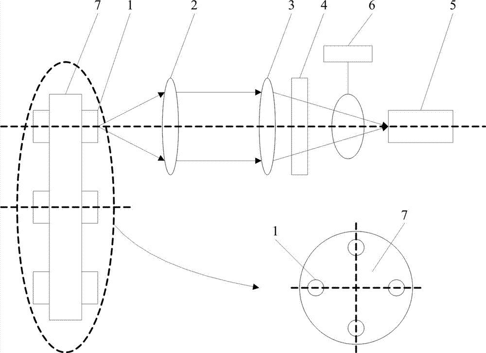
[0036] The structural schematic diagram of the near-infrared household food detection device of this embodiment is as follows: figure 2 As shown, the device is provided with a near-infrared light-emitting diode 1, a collimating objective lens 2, a focusing lens 3, an optical filter 4 and a detector 5 in sequence along the optical axis; the near-infrared light emitted by the near-infrared light-emitting diode 1 passes through the collimating objective lens 2 Parallel emission after collimation, then converge on the detector 5 through the focusing lens 3; the near-infrared light-emitting diode 1 is arranged at the focus position of the collimating objective lens 2, and the intermediate position between the optical filter 4 and the detector 5 On the top, there is a sample rack 6; the detector 5 is provided with a USB interface connected to a computer, and is connected to the computer through a USB cable.

[0037] In the above-mentioned near-infrared household food detection devi...

specific Embodiment 3

[0044] The structural schematic diagram of the near-infrared household food detection device of this embodiment is as follows: figure 2 As shown, the device is provided with a near-infrared light-emitting diode 1, a collimating objective lens 2, a focusing lens 3, an optical filter 4 and a detector 5 in sequence along the optical axis; the near-infrared light emitted by the near-infrared light-emitting diode 1 passes through the collimating objective lens 2 Parallel emission after collimation, then converge on the detector 5 through the focusing lens 3; the near-infrared light-emitting diode 1 is arranged at the focus position of the collimating objective lens 2, and the intermediate position between the optical filter 4 and the detector 5 On the top, there is a sample rack 6; the detector 5 is provided with a USB interface connected to a computer, and is connected to the computer through a USB cable.

[0045] In the above-mentioned near-infrared household food detection devi...


PUM

PropertyMeasurementUnit
wavelengthaaaaaaaaaa

Abstract

The invention discloses a near infrared household food detection device and method, and belongs to a food detection device and method by utilizing optical absorption characteristics of organic ingredients of food in a near infrared spectrum area. According to the device, near infrared rays emitted by a near infrared light emitting diode are collimated and emitted in parallel through a collimator objective and are converged to a detector through a focusing lens; a sample rack is arranged above a middle position between an optical filter and the detector; the detector is provided with an interface connected with a computer. The method comprises the following steps: adjusting the position of the near infrared light emitting diode, so that the emitted near infrared rays are received by the detector; suspending a sample to be detected on the sample rack; arranging the optical filter, so as to obtain a detection result of the sample to be detected under a particular wavelength; finally, analyzing the detection result according to the conventional technology, so as to obtain a detection conclusion. A filtering effect is improved, the device has a detection function under different wavelengths, and the influence of a container loading the sample to be detected on a measurement result is avoided. In addition, the device has high upgradeability and high extensibility.

Description

technical field [0001] The near-infrared household food detection device and method belong to the food detection device and detection method utilizing the optical absorption characteristics of food organic components in the near-infrared spectrum region. Background technique [0002] The near-infrared food quality detection device is based on the optical absorption characteristics of various representative organic components in the near-infrared spectral region in meat, edible oil and other foods, the difference in the strongest absorption wavelength of each component, and the difference between the absorption intensity and the organic properties of food. The proportional relationship between the content, through the regression analysis of the known chemical composition content of the sample and its near-infrared spectrum measurement results, establishes a calibration equation, and can estimate the content of the unknown sample composition of the same type. Due to the weak a...

Claims


Application Information

Patent Timeline
Patent Type & Authority Applications(China)
IPC IPC(8): G01N21/359G01N21/01G01N21/15
CPCG01N21/359
Inventor 赵春城赵烟桥
Owner WUXI X RES PROD DESIGN & RES
Why Eureka
Try Eureka