
Circular polarized antenna

A circularly polarized antenna and antenna unit technology, applied in the field of satellite communications, can solve problems such as inability to radiate or receive circularly polarized electromagnetic waves, complex antenna structure, thick antenna, etc., to achieve easy control of the amplitude, weighted antenna diameter, and weight Reduced effect

Active Publication Date: 2014-01-01
CHINA ELECTRONIC TECH GRP CORP NO 38 RES INST
View PDF8 Cites 12 Cited by
  • Summary
  • Abstract
  • Description
  • Claims
  • Application Information

AI Technical Summary

Problems solved by technology

However, the structure of this antenna is relatively complicated, including a two-layer structure of a feed waveguide and an open radiation waveguide. The antenna is thick and heavy.
The ridge waveguide inclined slot pair antenna (Chinese patent, CN200910184962.6) proposed by Wang Wei, Zhang Hongtao and others has a simple structure and can form standing wave and traveling wave antenna arrays, but this is a linearly polarized antenna that cannot radiate or receive circular polarized electromagnetic waves

Method used


Image

  • Circular polarized antenna
  • Circular polarized antenna
  • Circular polarized antenna

Examples


Embodiment 1

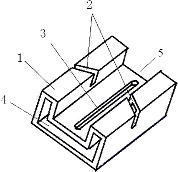
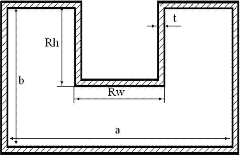
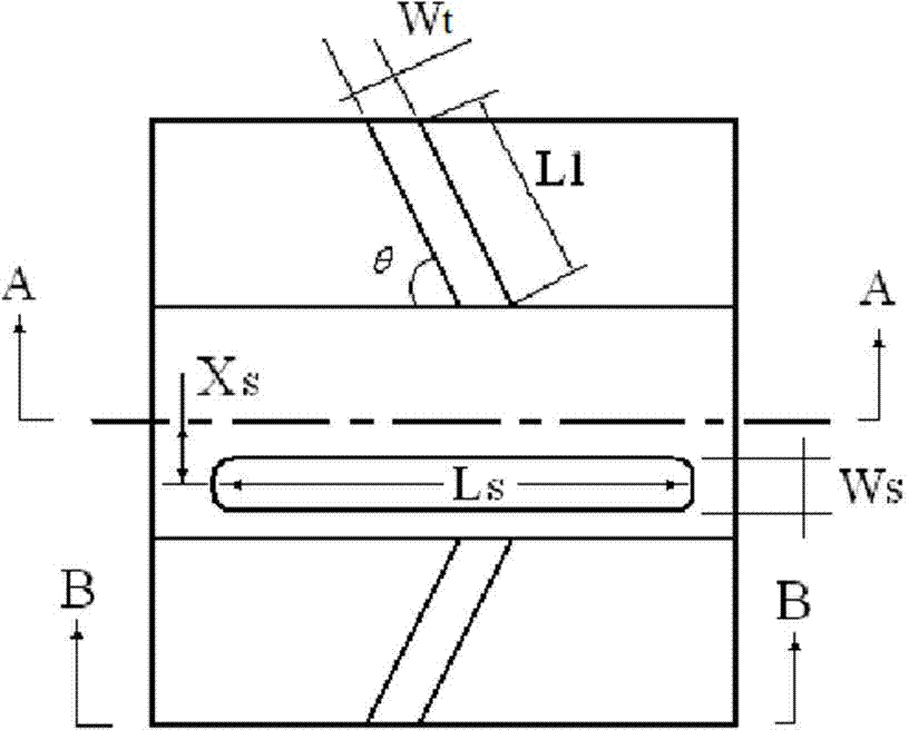
[0036] see figure 1 , a circularly polarized antenna working in the X-band, the center frequency is 10GHz, and the upper and lower side frequencies are 9.5GHz and 10.5GHz. The circularly polarized antenna consists of an antenna unit. The metal waveguide 1 of the circularly polarized antenna is a hollow single-ridge metal waveguide with a "concave" cross section, one end is the input end 4, and the other end is the output end. 5. Diagonal slots 2 are provided on the upwardly protruding narrow metal walls on both sides of the metal waveguide 1. The oblique slots 2 on both sides are mirror-image symmetrical, and the oblique slots 2 and the longitudinal axis of the metal waveguide 1 are clamped. Angle θ; a straight slit 3 is opened on the horizontal tube wall in the groove of the metal waveguide 1, and the straight slit 3 is parallel to the centerline of the metal waveguide, and between the straight slit 3 and the centerline of the metal waveguide 1 along the length direction An ...

Embodiment 2

[0056] see Image 6 , the present embodiment is a circularly polarized waveguide standing wave antenna array composed of four uniformly distributed X-band antenna elements, the center frequency is 10 GHz, and the upper and lower side frequencies are 9.5 and 10.5 GHz. In practical applications, it is usually necessary to arrange a plurality of antenna units with the same structure as required to form an antenna array.

[0057] The circularly polarized waveguide standing wave antenna array is composed of 4 antenna units connected end to end in turn, one end is the input end 4, the other end is the output end 5, the output end 5 is a metal short-circuit surface, and the distance between the short-circuit surface and the center of the nearest seam is 0.25λ g0 . The input terminals 4 of adjacent antenna units are connected or the output terminals 5 of adjacent antenna units are connected; the diagonal slits 2 on both sides of adjacent antenna units are mirror-symmetrically distrib...

Embodiment 3

[0071] see Figure 12 , in this embodiment, the antenna works in the X-band, the center frequency is 10 GHz, and the upper and lower side frequencies are 9.5 and 10.5 GHz. Using the antenna in Embodiment 1 as a basic unit, a total of 16 units constitute a circularly polarized waveguide standing wave antenna array, and the 16 circularly polarized antennas are axially cascaded, and the distance between the units is the same, which is 0.5λ g0 , the adjacent oblique slots 2 are arranged in a mirror image, the adjacent straight slots 3 are staggered and offset along both sides of the groove center line, the input end 4 and the output end 5 of the two waveguides are both short-circuited, and the same The axis 6 is fed and excited to form a center-fed circularly polarized standing wave antenna array. The method for selecting antenna size parameters in this embodiment is the same as that in Embodiment 2, and the connection method between the coaxial line 6 and the waveguide is well k...


PUM


Abstract

The invention relates to a circular polarized antenna. A metal waveguide tube of the antenna is the hollow single-ridge metal waveguide tube with the cross section in a shape like the Chinese character 'ao'. One end of the metal waveguide tube is the input end, and the other end of the metal waveguide tube is the output end. The metal walls of upward-protruded narrow sides on the two sides of the metal waveguide tube are respectively provided with an oblique slot. The oblique slots on the two sides of the metal waveguide tube are in mirror symmetry. An included angle between each oblique slot and the longitudinal axis of the metal waveguide tube is theta. A straight slot parallel to the central line of the metal waveguide tube is formed in the horizontal tube wall in a groove of the metal waveguide tube. The eccentric distance is formed between the straight slot and the central line of the metal waveguide tube in the length direction. The geometric center of the two oblique slots in mirror symmetry and the geometric center of the straight slot are located in the same cross section of the metal waveguide tube. The circular polarized antenna is simple in structure, easy to machine and light in weight. Compared with CN 200910184962.6, the weight is reduced by about half when the circular polarized antennas form an antenna array. The port of the output end of the metal waveguide tube of the antenna is short-circuited through metal or is connected and matched with a load so that a standing wave antenna array or a traveling wave antenna array can be conveniently obtained.

Description

technical field [0001] The invention belongs to the antenna technology in the field of satellite communication, and in particular relates to a metal ridge waveguide circularly polarized antenna. Background technique [0002] Antenna is an essential device in a radio system, and there are various forms of antenna implementation. Antennas are divided according to the polarization mode of work. There are mainly two types of linear polarization and circular polarization. Among them, linear polarization includes horizontal polarization, vertical polarization and oblique polarization, etc., while circular polarization mainly includes left-handed circular polarization and There are two kinds of right-handed circular polarization. Circularly polarized antennas are widely used in satellite communications, weather radar, electronic reconnaissance and countermeasures. In circularly polarized antennas for satellite communications and data transmission, waveguide slot antennas have obv...

Claims


Application Information

Patent Timeline
Patent Type & Authority Applications(China)
IPC IPC(8): H01Q13/22H01Q21/00
Inventor 汪伟齐美清张洪涛金谋平邹永庆
Owner CHINA ELECTRONIC TECH GRP CORP NO 38 RES INST
Learn More