High-performance microwave sputtering plate feeder antenna

A technology of sputtering plate and feed source, which is applied in the field of microwave antenna design and technology, can solve the problems of broadband lobe equalization affecting the antenna, inability to solve multi-band transmission and reception, unsatisfactory terminal matching, etc., and shorten the supply time. The effect of cycle, saving manpower and material resources, and small number of components

Inactive Publication Date: 2018-07-13
SHAANXI EVSAT SCI & TECH DEV +1
View PDF9 Cites 1 Cited by
  • Summary
  • Abstract
  • Description
  • Claims
  • Application Information

AI Technical Summary

Problems solved by technology

[0004] The main problem of the current splatter plate feed antenna is that the terminal matching of the radiation waveguide of the feed opening is not ideal, resulting in a relatively high voltage standing wave
Moreover, since the feed source of the splash plate feed antenna is mostly a light-walled circular waveguide, when the frequency increases, the discontinuity at the waveguide opening excites and propagates harmful waveguide modes in the waveguide, which affects the broadband lobes of the antenna, etc. characteristics
The existing solution is to increase the pin cone or columnar step matching transition, but it can only solve the narrower frequency band matching, and cannot solve the problem of wide-band transceiver or even multi-band transceiver in satellite communication.

Method used


Image

  • High-performance microwave sputtering plate feeder antenna
  • High-performance microwave sputtering plate feeder antenna
  • High-performance microwave sputtering plate feeder antenna

Examples


Embodiment Construction

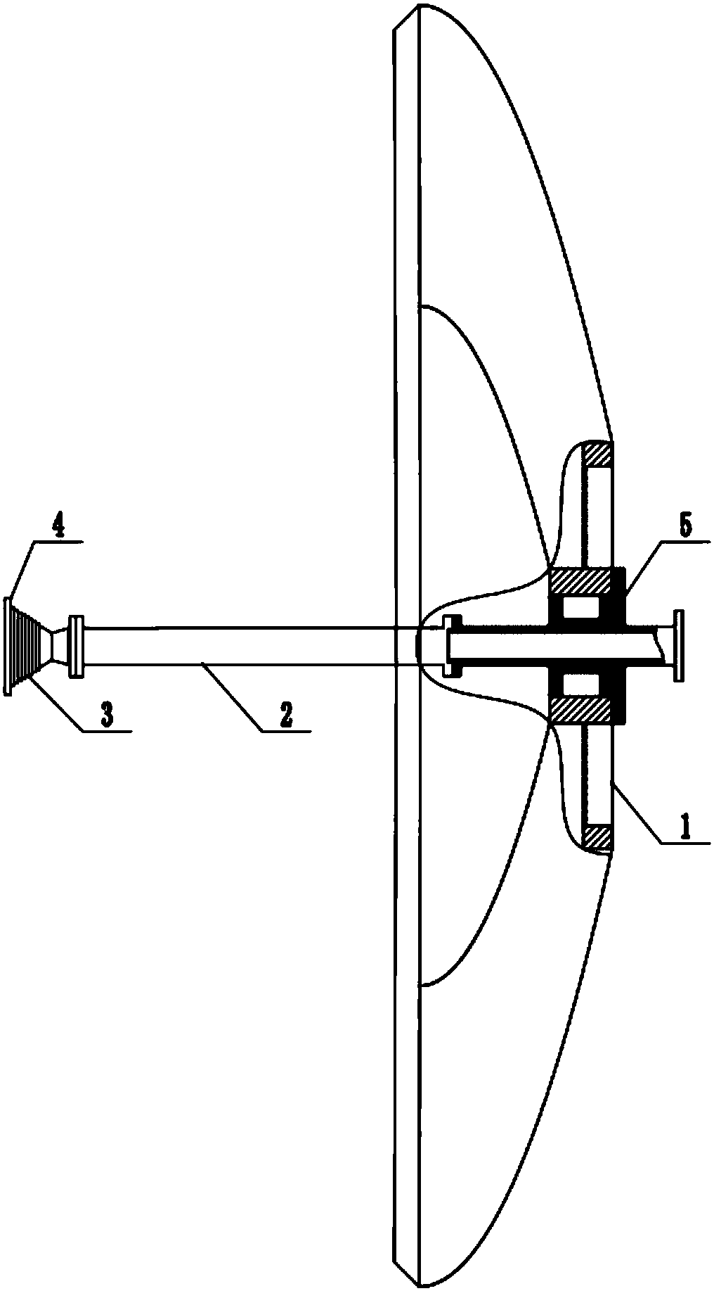
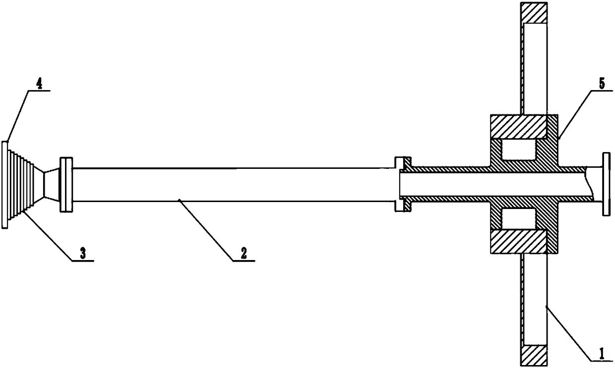
[0033] This embodiment provides a high-performance microwave scatter plate feed antenna, including:

[0034] A split portable main reflector (1) formed by a carbon fiber standard paraboloid formed by cold pressing of a mold;

[0035] A circular waveguide (2) that is fed into sections along the axis of the main reflector;

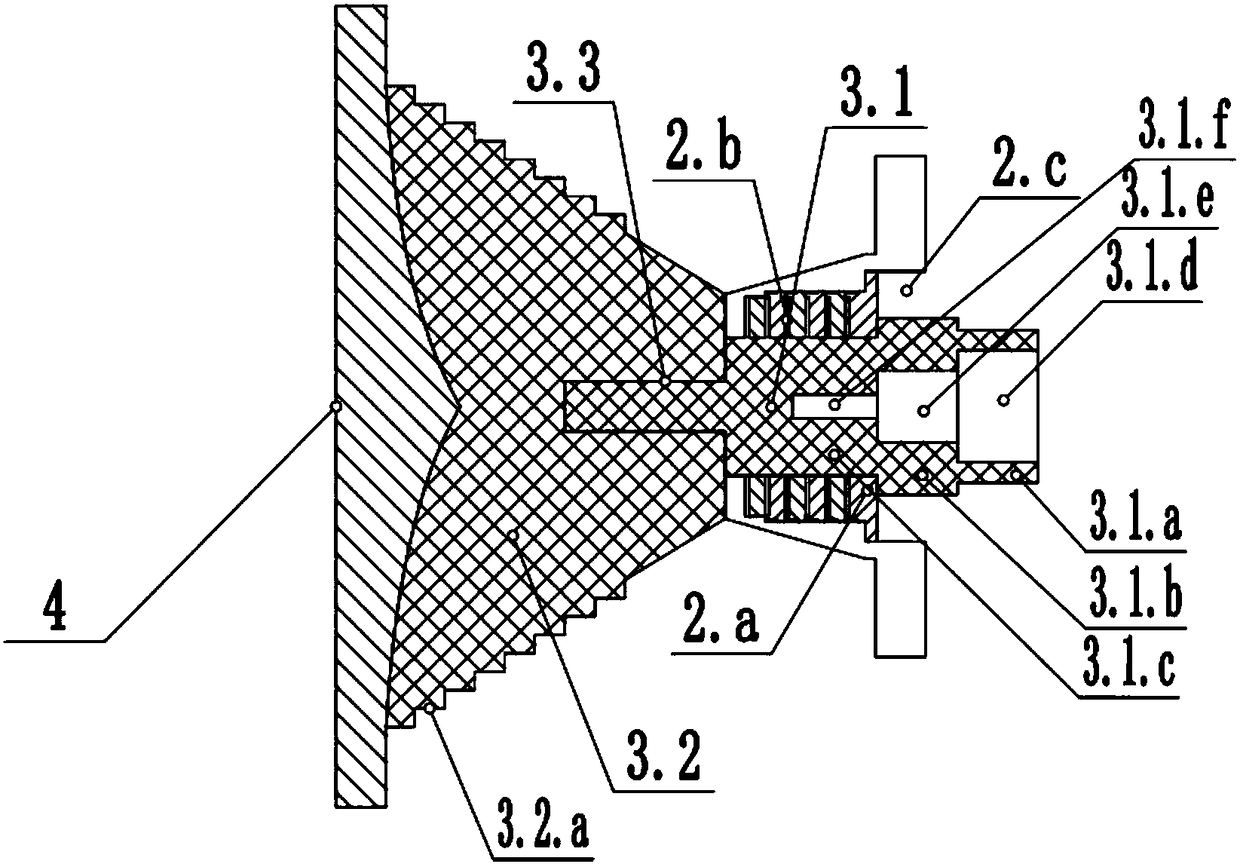
[0036] A shaped rotationally symmetrical dielectric splash plate (3), which is located above the circular waveguide (2);

[0037] A sub-reflector (4) formed on the bottom surface of the dielectric splash plate (3) through a metal sheet;

[0038] a feed connecting waveguide (5) connecting the circular waveguide (2) and the main reflector (1);

[0039] In the process of energy transmission, the circular waveguide (2) emits spherical wave energy first, and the spherical wave energy is transmitted to the dielectric sputtering plate (3) and reaches the sub-reflector (4) after multiple reflections and refractions, and then the sub-reflector (4). The reflector (...


PUM


Abstract

The invention discloses a high-performance microwave sputtering plate feeder antenna, comprising: a split portable main reflector formed by a carbon fiber standard paraboloid formed by die cold pressing; a circular waveguide tube connected along an axial feeder segment of the main reflector; a shaped dielectric sputtering plate in rotational symmetry which is positioned above the circular waveguide tube; an auxiliary reflector arranged at the bottom of the dielectric sputtering plate and formed of a metal sheet; a feeder connection waveguide that allows the circular waveguide tube to be connected with the main reflector. The high-performance microwave sputtering plate feeder antenna has better performance, is portable and attractive and is low in cost.

Description

technical field [0001] The invention belongs to the technical field of microwave antenna design and technology, and in particular relates to the design and technology of sputtering plate antennas in the Q, Ka, Ku and X frequency bands of small-diameter antennas in satellite communication systems. technical background [0002] The scatter plate feed antenna belongs to the dual reflector rear feed antenna. Compared with the traditional Cassegrain, Gregorian and ring-focus antennas, the splash plate feed antenna has a main reflector that does not need to be shaped, but only supports the surface of the medium and the secondary reflector, so it can control the antenna port The amplitude distribution of the surface can be controlled, and the phase distribution can be controlled to achieve an antenna pattern with high gain, low sidelobe, and low cross-polarization. And the scatter plate feed antenna is supported by the medium, and the scatter plate is used as the sub-reflector, th...

Claims


Application Information

Patent Timeline
IPC IPC(8): H01Q1/12H01Q1/50H01Q13/00H01Q15/14H01Q15/16H01Q19/19
Inventor 艾宇涛
Owner SHAANXI EVSAT SCI & TECH DEV
Why Eureka
Try Eureka