A control method for thyristor reverse recovery period protection by valve control system

A technology of reverse recovery period and valve control system, applied in emergency protection circuit devices, electrical components, power transmission AC network, etc. problems, to achieve the effect of reducing false triggering, ensuring correctness, and reducing the probability of occurrence

Active Publication Date: 2016-01-20
XJ ELECTRIC
View PDF3 Cites 0 Cited by
  • Summary
  • Abstract
  • Description
  • Claims
  • Application Information

AI Technical Summary

Problems solved by technology

[0007] The purpose of the present invention is to provide a control method for the protection of the reverse recovery period of the thyristor by the valve control system, so as to solve the problem that the current operating valve control system does not distinguish the function of starting the reverse recovery period protection, so that under special circumstances, the temporary failure of the system state perturbation causes no departure problem

Method used


Image

  • A control method for thyristor reverse recovery period protection by valve control system
  • A control method for thyristor reverse recovery period protection by valve control system
  • A control method for thyristor reverse recovery period protection by valve control system

Examples


Embodiment Construction

[0020] The specific embodiments of the present invention will be further described below in conjunction with the accompanying drawings.

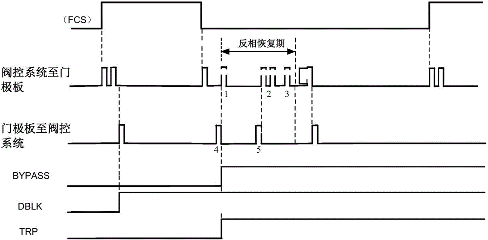
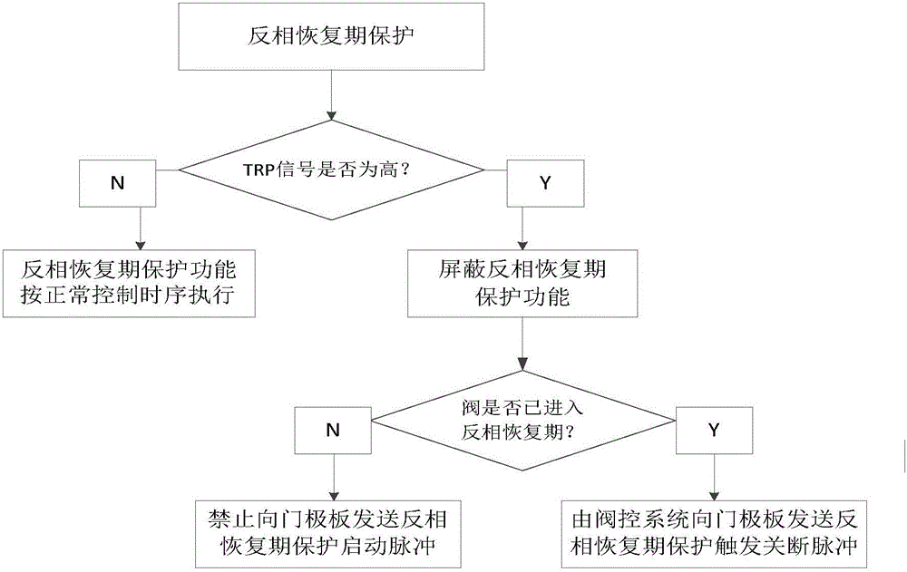
[0021] The valve control system controls the operating state of the gate plate by sending pulse signals to the gate plate, and then realizes the function of controlling the switching on and off of the thyristor of the converter valve. The valve control system mentioned here refers to the converter valve control equipment, the gate plate is the control unit of the thyristor level. The flow diagram and timing diagram of its signal are as follows figure 1 As shown, where FCS represents the converter valve trigger control signal; BYPASS represents the converter valve bypass effective signal; DBLK represents the converter valve unlock signal; TRP represents the reverse recovery period protection control signal.

[0022] The work of the valve control system and the gate plate adopts five-pulse coding, and the control principle of five-pulse codi...


PUM


Abstract

The invention relates to a control method using a valve control system to carry out reversed recovery-stage protection on a thyristor and belongs to the technical field of high-voltage DC transmission of an electric system. According to the control method, the startup range of a reversed recovery stage of the thyristor is controlled by adding logical judgment conditions, and consequently the condition that the protection function of the thyristor in the reversed recovery stage can be controlled under different working conditions is achieved. The control method ensures that the protection functions of the valve control system in an original reversed recovery stage is not influenced, and the situation that reversed recovery-stage protection actions of the thyristor in the reversed recovery stage cause failure of a bypass pair or generation of excessive current under some special working conditions is also avoided. Consequently, the purpose that the valve control system can control and optimize the protection functions of the thyristor in the reversed recovery stage is achieved.

Description

technical field [0001] The invention relates to a control method for the reverse recovery period protection of a thyristor by a valve control system, and belongs to the technical field of high-voltage direct current transmission of electric power systems. Background technique [0002] In HVDC transmission, the triggering of reverse recovery period protection plays a very important role in the safe and stable operation of the converter valve and even the entire converter station system. [0003] Equipment failure or some operations in the converter station may cause a very steep forward transient voltage at both ends of the thyristor within a short time after the converter valve is shut down. This transient high voltage may cause the thyristor to be forced to strike. worn and damaged. This is because, when the thyristor is reliably turned off, it can withstand the forward blocking voltage, and its ability to withstand the reverse recovery period is very high, and in the reve...

Claims


Application Information

Patent Timeline
Patent Type & Authority Patents(China)
IPC IPC(8): H02J3/36H02H7/122
CPCY02E60/60
Inventor 姚为正胡四全董朝阳孟学磊罗鹏
Owner XJ ELECTRIC
Why Eureka
Try Eureka