
Variable shortwave antenna tuner matching network structure circuit

A technology of network structure and antenna adjustment, applied in antennas, electrical components, transmission systems, etc., can solve the problems of not adapting to antenna impedance characteristics, increasing radio frequency power loss, increasing antenna power loss, etc., achieving flexible use and improving reliability , the effect of strong adaptability

Active Publication Date: 2014-01-01
PANDA ELECTRONICS GROUP +1
View PDF5 Cites 26 Cited by
  • Summary
  • Abstract
  • Description
  • Claims
  • Application Information

AI Technical Summary

Problems solved by technology

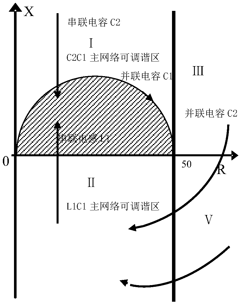
But in fact, it is impossible for the antenna to be inductive or capacitive in the whole frequency band, so a secondary network is usually added near the antenna end of the antenna to adjust the impedance of the antenna, so that the impedance range of the antenna can be adjusted in the main network of the antenna area, but the available value of the sub-network is very limited, which may increase the power loss of the tuner
Moreover, with the development of antenna technology, there are more and more types of antennas, and the impedance characteristics are becoming more and more complex. A single CC network or LC network is no longer suitable for complex antenna impedance characteristics, and instead increases the RF power on the antenna. loss

Method used


Image

  • Variable shortwave antenna tuner matching network structure circuit
  • Variable shortwave antenna tuner matching network structure circuit

Examples


Embodiment Construction

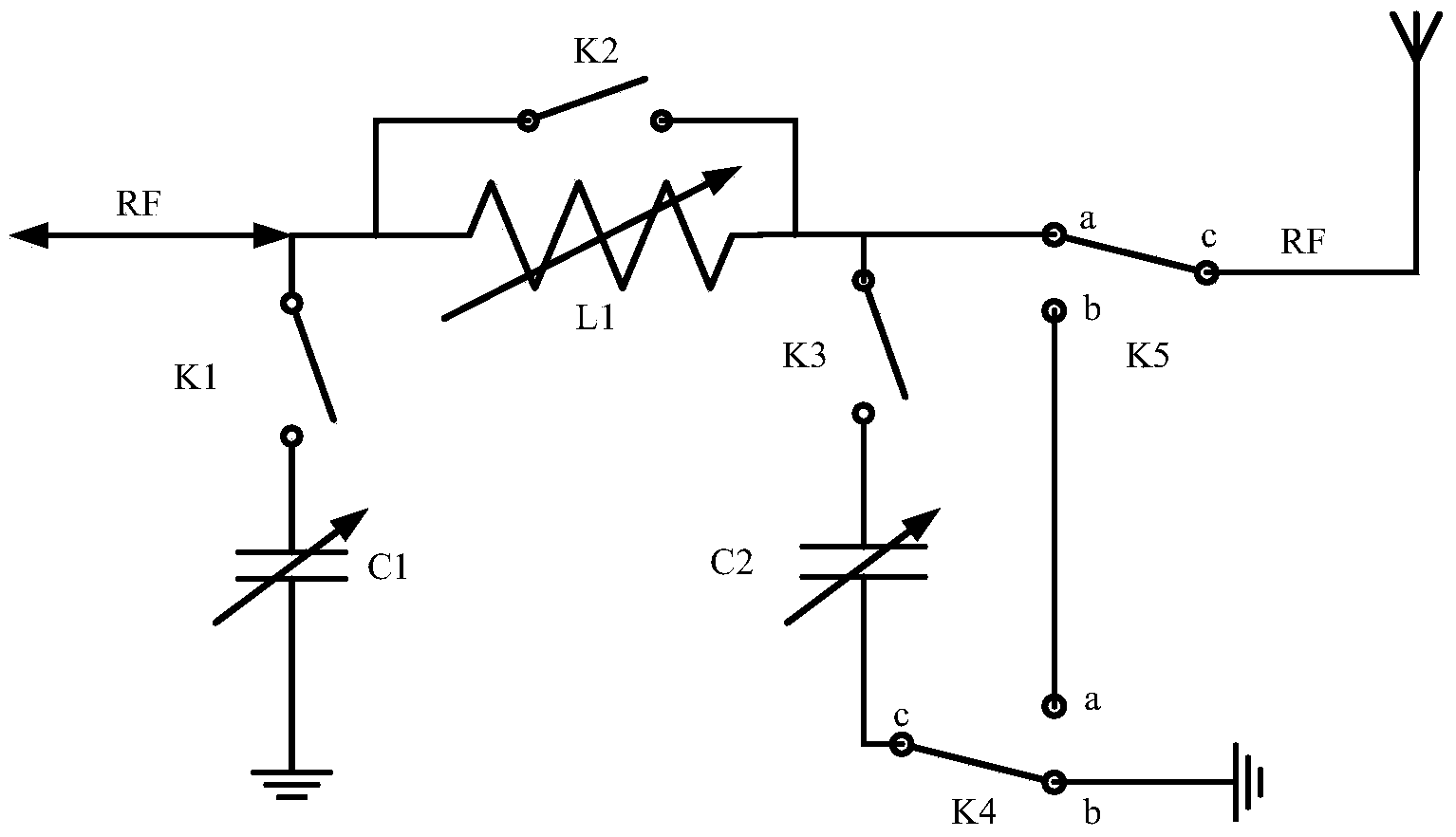
[0013] The schematic diagram of the structural design of the variable tune matching network in the present invention is as follows: figure 1 As shown, C1 and C2 in the figure are formed by parallel connection of 10 multiplied discrete capacitors. The value range of C1 is 0-5120pF with a value accuracy of 5pF, and the value range of C2 is 0-2048pF. The value accuracy is 2pF; L1 in the figure is composed of 10 multiplied discrete inductors connected in series, the value range of L1 is 0~32uH, and the value accuracy is 0.03uH; the relay-controlled switches K1, K2, K3 It is to control whether each discrete inductor or capacitor corresponding to the network is connected to the network. The switches K4 and K5 controlled by the relay switch the serial-parallel mode of C2 in the network. When K4 hits the b terminal, K5 hits Terminal a, then C2 is connected to the network in parallel; when K4 is connected to terminal a and K5 is connected to terminal b, C2 is connected to the network i...


PUM


Abstract

Provided is a variable shortwave antenna tuner matching network structure circuit. A set of series inductor is connected with a radio frequency antenna, the two ends of the series inductor are connected with a set of first grounding capacitor and a set of second grounding capacitor in parallel respectively, switches controlled by a relay are connected on the first capacitor and the second capacitor in series, and a short circuit switch controlled by the relay is also connected on the inductor in parallel. The second grounding capacitor connected with the radio frequency antenna is selected to be in grounding connection through a switching switch or to be directly connected with the radio frequency antenna through a wire. The radio frequency antenna is also connected with a switching switch which is used for selecting the connecting positions of the series inductor and the parallel grounding capacitors or being connected with the second grounding capacitor which is directly connected with the radio frequency antenna through the wire. When the circuit is in parallel connection, the circuit can be used as the auxiliary network of an LC network structure, and when the circuit is in series connection, the circuit can be used as the main network of a CC network structure. The circuit is flexible in use, strong in adaption capacity and small in power loss.

Description

1. Technical field [0001] The invention belongs to the design of electronic circuits, in particular to the design of variable pitch matching network structure circuits. 2. Background technology [0002] The short-wave antenna tuner (hereinafter referred to as the antenna tuner) is to realize the impedance matching between the transmitter and the antenna, so that the power of the transmitter can be transmitted to the antenna to the maximum extent. The matching network of Tiantun is composed of multiple sets of inductors and capacitors. It is a lossless network in theory, but in fact, it is impossible to achieve idealization of capacitors and inductors. There must be parasitic impedance, especially large inductors will heat up during use. , indicating that part of the radio frequency power is converted into heat energy inside the tuner. In addition, the narrower the matching bandwidth of the network at each frequency point, the influence of the value range and accuracy of the...

Claims


Application Information

Patent Timeline
IPC IPC(8): H04B1/40H01Q23/00H04B1/401
Inventor 刘科伟姜孝伟朱明皓程凯
Owner PANDA ELECTRONICS GROUP
Learn More