Multi-frequency matching device and plasma device

A matcher and plasma reaction technology, applied in the field of plasma, can solve the problems that the matcher 103 cannot work normally, damage the RF power supply and other devices, and the low isolation of the input port, so as to achieve ideal isolation, eliminate interference, and high matching range Effect

Active Publication Date: 2017-10-20
BEIJING NAURA MICROELECTRONICS EQUIP CO LTD
View PDF7 Cites 0 Cited by
  • Summary
  • Abstract
  • Description
  • Claims
  • Application Information

AI Technical Summary

Problems solved by technology

Moreover, there must be interference between the two radio frequency power supplies, the light one will make the matching device 103 not work normally, and the severe one will damage the radio frequency power supply and other devices
[0008] Not only that, there are setting requirements for the frequency range of the RF power connected to the matcher 103, and the matching range is limited; the isolation of multiple input ports of the matcher 103 is very low

Method used


Image

  • Multi-frequency matching device and plasma device
  • Multi-frequency matching device and plasma device
  • Multi-frequency matching device and plasma device

Examples


Embodiment Construction

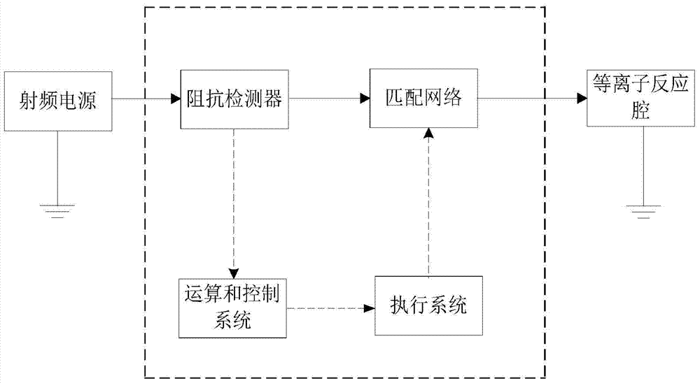
[0037] In order to solve the problems of large size, small matching range and mutual interference, a multi-frequency matching device and a plasma device are proposed to realize it.

[0038] The above and other technical features and advantages of the present invention will be described in more detail below in conjunction with the accompanying drawings.

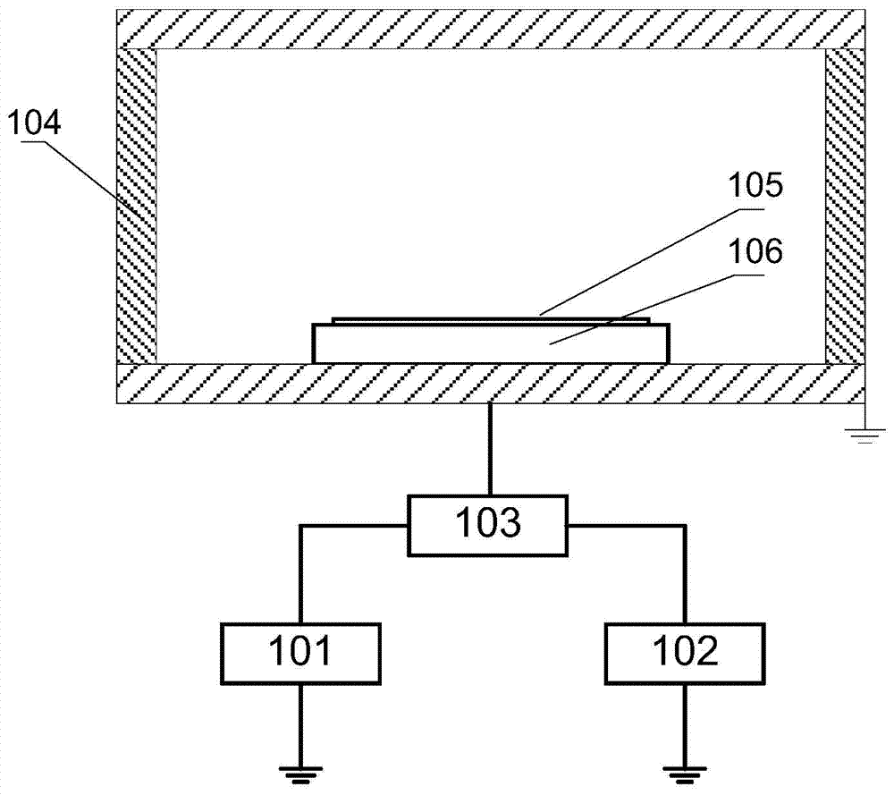
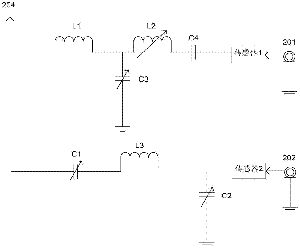
[0039] The multi-frequency matching device of the embodiment of the present invention includes a low-frequency circuit and a high-frequency circuit connected in parallel with each other. A first inductance L1 is provided at the end of the low-frequency circuit close to the plasma reaction chamber (that is, the output end), and a first inductor L1 is set at the end of the high-frequency circuit close to the plasma reaction chamber. One end of the cavity (ie, the output end) is provided with a first capacitor C1.

[0040] One end of the first inductor L1 is electrically connected to the plasma reaction chamber, and the other end...


PUM


Abstract

The invention relates to a multi-frequency matching device and a plasma device. The multi-frequency matching device includes a low-frequency circuit and a high-frequency circuit connected in parallel, and a first inductance is connected in series on the low-frequency circuit; a first inductance is connected in series on the high-frequency circuit. Capacitor; one end of the first inductor is electrically connected to the plasma reaction chamber, and the other end is electrically connected to the low-frequency power supply; one end of the first capacitor is electrically connected to the plasma reaction chamber, and the other end is electrically connected to the high-frequency power supply. The plasma device includes a plasma reaction chamber, a high-frequency power supply, a low-frequency power supply and the multi-frequency matching device; the upper electrode and the lower electrode of the plasma reaction chamber are electrically connected to the low-frequency circuit and the high-frequency circuit of the multi-frequency matching device respectively. A circuit; the low frequency circuit or the high frequency circuit is electrically connected to the low frequency power supply and the high frequency power supply, respectively. Through the above design, the purpose of small size, large matching range and high isolation between the two input ports is achieved.

Description

technical field [0001] The invention relates to a plasma technology, in particular to a matcher connected to multiple radio frequency power sources at the same time and a plasma device with a multi-frequency matcher. Background technique [0002] In the prior art, plasma technology is widely used in the fields of semiconductor, flat panel display, solar energy and industry. In the plasma etching and sputtering system, the RF power supply delivers RF energy to the plasma reaction chamber to generate plasma. The plasma contains a large number of active particles such as electrons, ions, excited atoms, molecules and free radicals. These active particles interact with the wafer placed in the cavity and exposed to the plasma environment, causing the surface of the wafer material to Various physical and chemical reactions, so that the surface properties of the material change, and the etching, sputtering or other processes of the wafer are completed. [0003] see figure 1 As sh...

Claims


Application Information

Patent Timeline
Patent Type & Authority Patents(China)
IPC IPC(8): H05H1/46H01J37/32
Inventor 师帅涛陈鹏张超
Owner BEIJING NAURA MICROELECTRONICS EQUIP CO LTD
Why Eureka
Try Eureka