Method and system for cooperatively locating heterogeneous network based on WLAN and WSN

A heterogeneous network and collaborative positioning technology, applied in the field of communication, can solve the problems that the reliability and stability are greatly affected by environmental factors, and the positioning accuracy of WSN is not high, so as to achieve the effects of improving anti-interference ability, fast and accurate positioning, and reducing costs

Inactive Publication Date: 2014-01-01
MAIPU COMM TECH CO LTD
2 Cites 24 Cited by

AI-Extracted Technical Summary

Problems solved by technology

[0008] The technical problem to be solved by the present invention is to overcome the defects in the prior art that only using the wireless local area network WLAN or the wireless sensor network WSN positioning accuracy is not high, and the ...

Method used

But because APIT algorithm also has certain defect, in the middle part of network coverage area, the neighbor beacon node of unknown node has a lot, but may not have a triangle that is made up of 3 neighbor beacon nodes and can comprise this unknown node, This causes these unknown nodes to become undetermined nodes after running the positioning algorithm; at the edge of the network coverage area, unknown nodes have relatively few neighbor beacon nodes, which makes it easier for them to fail to meet the APIT positioning conditions, and even some nodes' The number of neighbor beacon nodes is less than 3, and they will all become undetermined nodes,...

Abstract

The invention discloses a method and system for cooperatively locating a heterogeneous network based on WLAN and a WSN. The method comprises the following steps that a WLAN and WSN mixed locating system for the heterogeneous network is built in a locating area; N sets of data closest to the sampling information of a node to be measured are selected through a WLAN locating technology; the position of the node to be measured is estimated based on a WSN locating technology; cooperative locating is carried out through the WLAN and the WSN, the data selected through the WLAN technology are compared with estimation coordinates in the WSN locating technology, and the set of closest position information is selected as the final estimation position of the node to be measured. According to the method and the system, the advantages that WSN networking is flexible and WLAN network transmission speed is high are effectively combined, all technical defects are avoided, through the existing WLAN, the existing WSN and the designed network fusion algorithm, locating precision is obviously improved, and meanwhile signal flying value points caused by a complex and changeable environment can be removed.

Application Domain

Technology Topic

Image

  • Method and system for cooperatively locating heterogeneous network based on WLAN and WSN
  • Method and system for cooperatively locating heterogeneous network based on WLAN and WSN
  • Method and system for cooperatively locating heterogeneous network based on WLAN and WSN

Examples

  • Experimental program(1)

Example Embodiment

[0036] The present invention will be further elaborated below in conjunction with the accompanying drawings and specific embodiments.
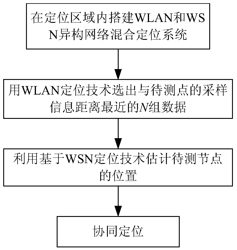
[0037] like figure 1 Shown is a flow chart of a heterogeneous network co-location method based on WLAN and WSN according to an embodiment of the present invention, which specifically includes the following steps:
[0038] A. Build a hybrid positioning system in the positioning area:
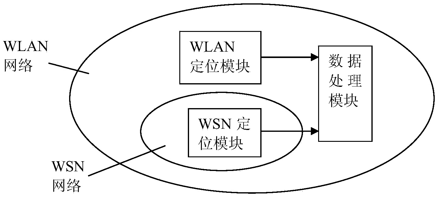
[0039] Set the wireless access point AP in the positioning area to build a wireless local area network WLAN; at the same time build a wireless sensor network WSN in the positioning area; In general, only 4 AP signals can be received. In actual operation and application, the existing WLAN network or WSN network can also be used without rebuilding the WLAN network or WSN network.
[0040] B. Use WLAN positioning technology to estimate the position of the node to be tested:
[0041] In the constructed WLAN network, the off-line data collection is carried out for the positioning area, the RSSI sample data of the reference nodes in the positioning area are obtained, the location fingerprint information of the reference node is obtained, and the obtained location fingerprint information is stored in the location fingerprint database; Perform real-time positioning measurement in the area, obtain RSSI measurement data of surrounding APs from unknown nodes, compare the RSSI measurement data with the RSSI sample data in the database, and filter out N groups of data in the location fingerprint database that are closest to the RSSI measurement data;
[0042] The specific operation steps are:
[0043] B1. Offline data collection in the positioning area: select a certain number of reference nodes in the positioning area. The selection of the number of reference nodes can be changed according to the positioning accuracy required, but try to select enough reference nodes to cover the entire positioning area. , so that the obtained fingerprint database can include the location fingerprint information in the positioning area as much as possible; the RSSI sample data is collected multiple times on the selected reference nodes, and the RSSI values ​​​​measured by each AP on these reference nodes are carried out. Average processing to form a group of RSSI elements, and store the group of RSSI elements as the location fingerprint samples of the reference node in the location fingerprint database. When positioning is required next time, the RSSI sample data in the existing fingerprint database can also be used, and No need for repeated measurements;
[0044] B2. Real-time positioning measurement of the positioning area: the unknown node collects the RSSI value of its surrounding APs to form a set of RSSI measurement data of APs, and then screens and matches through the relationship between the RSSI measurement data and the location fingerprint database. For details, see Step B2;
[0045] B3, data screening is carried out to the obtained RSSI sample data and RSSI measurement data: assume that the RSSI information collected by the node to be measured to the surrounding APs in the positioning phase is S, and the S={S 1 , S 2 ,...,S n}, R is the RSSI feature value information of the position of the reference node in the position fingerprint database, and the R={β 1 , β 2 ,...,β n}, where, n is the number of access AP points; according to D ( S , R ) = ( S 1 - β 1 ) 2 + ( S 2 - β 2 ) 2 + . . . + ( S n - β n ) 2 ≤ ΔD To select N sets of location information data with the closest matching degree to the actual received signal, ΔD is the fixed threshold value of the information distance we set, which can be determined according to the hardware situation and positioning accuracy. Alternatively, in the location fingerprint database, the location fingerprint information of m reference nodes is included, and its set is A={R 1 ,R 2 ,...,R m}, according to D(S,R j )≤D(S,R k ), select the N groups of data closest to the sampling information in the location fingerprint library, and the R j ∈A,R k ∈A, for all k≠j, iterate m times. The above-mentioned specific screening process is a prior art, and will not be described in detail in the application scheme of the present invention.
[0046] C. Utilize WSN-based positioning technology to estimate the position of the node to be tested:
[0047] In the constructed WSN network, calculate the neighbor relationship between each node, estimate the position of the node to be measured according to the neighbor relationship between each node, set it as (x, y); realize the step C can be realized by two kinds of algorithms, The process of two algorithms to realize the position estimation of the node to be tested will be described in detail below:
[0048] 1. Use the APIT algorithm to estimate the position of the node to be tested. The specific process is:
[0049] C1. The node to be tested selects three neighbor beacon nodes that can communicate with it, and tests whether the node to be tested is outside or inside the triangle formed by the three neighbor beacon nodes;
[0050] C2. Repeat the above operation, select another three neighboring beacon nodes that can communicate with it to perform the same test, so that all combinations can be exhausted or the preset accuracy requirements can be reached. If the node to be tested is inside a triangle, it means that the triangle contains the node to be tested. measuring node;
[0051] C3. Take the centroids of the intersecting parts of all triangles containing the node to be measured as the estimated position of the node to be measured, and set it as (x, y).
[0052] However, because the APIT algorithm also has certain defects, in the middle of the network coverage area, there are many neighbor beacon nodes of the unknown node, but there may not be a triangle composed of three neighbor beacon nodes that can contain the unknown node, which causes These unknown nodes become undetermined nodes after running the positioning algorithm; at the edge of the network coverage area, unknown nodes have relatively few neighbor beacon nodes, which makes it easier for them to fail to meet the APIT positioning conditions, and even some nodes' neighbor beacon nodes If the number of nodes is less than 3, they will all become undetermined nodes, so the APIT algorithm needs to be improved. The improved algorithm is to locate the nodes that meet the APIT positioning conditions according to the APIT algorithm, and for the nodes that do not meet the APIT positioning conditions, do Further processing improves positioning coverage. When the number of neighbor beacon nodes around the node to be tested is greater than or equal to 3, the three-sided measurement method is used for positioning; when the number of neighbor beacon nodes is 2, the intersection point is obtained by geometrically calculating the circle intersection point as the test point The estimated position (x,y) of the node.
[0053]2. Use the DV-Hop algorithm to estimate the location of the node to be tested. The specific process is: the reference node broadcasts a beacon to the WSN network, which contains the location information of the reference node and a hop with an initial value of 1. The number of parameters; the receiving node saves the beacon with the smallest hop value among all the beacons received about a certain reference node, and discards the beacons of the same reference node with a larger hop value, and all nodes in the network have obtained The minimum hop value to each reference node; estimate the average physical distance of each hop in the network, and the reference node obtains the actual distance to other reference nodes according to the hop value to other reference nodes in the network and the location information of these reference nodes; The node obtains the average distance per hop of the network, and then broadcasts it to the network. The unknown node receives the average distance per hop, and estimates the distance from itself to the reference node; the unknown node obtains the estimated distance of more than three reference nodes, and uses trilateral measurement method to estimate its own position, which is set to (x, y).
[0054] D. Co-location:
[0055] The N groups of data selected in the step B are compared with the coordinates (x, y) of the estimated position of the node to be measured obtained in the step C, and the coordinates (x, y) are selected in the N groups of data. ) of the closest group of location information data (x i ,y i ) as the final estimated coordinates of the nodes to be measured, where r is required i 2 =(x i -x) 2 +(y i -y) 2 is the minimum, the r is the coordinates (x, y) and (x i ,y i )the distance between.
[0056] The present invention also provides a heterogeneous network co-location system based on WLAN and WSN, such as image 3 As shown, it includes: a WLAN network, a WSN network, a WLAN positioning module, a WSN positioning module, and a data processing module. The WLAN positioning module is used for offline data collection of the positioning area in the WLAN network, and obtains the RSSI of the reference node in the positioning area. Sample data, obtain the location fingerprint information of the reference node, and store the obtained location fingerprint information in the location fingerprint database; perform real-time positioning measurement on the positioning area, obtain the RSSI measurement data of the unknown node to the surrounding AP, and combine the RSSI measurement data with the database Compare the RSSI sample data in the location fingerprint library and filter out the N sets of data closest to the RSSI measurement data in the location fingerprint database;
[0057] The WSN positioning module is used to calculate the neighbor relationship between each node in the WSN network. According to the neighbor relationship between each node, the node to be tested selects three neighbor beacon nodes that can communicate with it, and the node to be tested is tested in these three neighbors. Whether the triangle formed by three neighbor beacon nodes is outside or inside; repeat the above operation, and select three other three neighbor beacon nodes that can communicate with it to perform the same test, so that all combinations can be exhausted or the preset accuracy requirements can be reached. If the node to be tested is inside a certain triangle, it means that the triangle contains the node to be tested; finally, take the centroids of the intersecting parts of all triangles containing the node to be tested as the estimated position of the node to be tested, and set it to (x, y);
[0058] The data processing module is used to compare the estimated position (x, y) of the node to be measured obtained by the WLAN positioning module with the N groups of data obtained by the WSN positioning module, and select the coordinates (x, y) in the N groups of data (x i ,y i ) as the final estimated coordinates of the nodes to be measured, where r is required i 2 =(x i -x) 2 +(y i -y) 2 is the minimum, the r is the coordinates (x, y) and (x i ,y i )the distance between.
[0059] Those skilled in the art will appreciate that the embodiments described here are to help readers understand the principles of the present invention, and it should be understood that the protection scope of the present invention is not limited to such specific statements and embodiments. Those skilled in the art can make various other specific modifications and combinations based on the technical revelations disclosed in the present invention without departing from the essence of the present invention, and these modifications and combinations are still within the protection scope of the present invention.

PUM

no PUM

Description & Claims & Application Information

We can also present the details of the Description, Claims and Application information to help users get a comprehensive understanding of the technical details of the patent, such as background art, summary of invention, brief description of drawings, description of embodiments, and other original content. On the other hand, users can also determine the specific scope of protection of the technology through the list of claims; as well as understand the changes in the life cycle of the technology with the presentation of the patent timeline. Login to view more.

Similar technology patents

Classification and recommendation of technical efficacy words

  • Improve anti-interference ability
  • High positioning accuracy
Why Eureka
Try Eureka