Linear switching constant-current LED drive circuit for control over peak current

A technology of LED driving and peak current, which is applied in the direction of electric lamp circuit layout, electric light source, lighting device, etc., can solve the problems of high chip heat generation, low system efficiency, and large power consumption, and achieve the purpose of improving excessive heat generation, improving light efficiency, Effect of system cost reduction

Active Publication Date: 2015-06-03
FREMONT MICRO DEVICES SHENZHEN LTD
View PDF6 Cites 1 Cited by
  • Summary
  • Abstract
  • Description
  • Claims
  • Application Information

AI Technical Summary

Problems solved by technology

[0003] The technical problem to be solved by the present invention is to provide a linear switch constant current LED drive circuit that controls the peak current, which can keep the average output current and average output power flowing through the LED lamp bead constant. Solve the problems of low system efficiency, excessive power consumption, and high chip heating when the input voltage of the existing linear constant current driver chip is high, and at the same time prolong the service life of the LED lamp bead and reduce the system cost

Method used


Image

  • Linear switching constant-current LED drive circuit for control over peak current
  • Linear switching constant-current LED drive circuit for control over peak current
  • Linear switching constant-current LED drive circuit for control over peak current

Examples


Embodiment Construction

[0020] In order to have a clearer understanding of the technical features, purposes and effects of the present invention, the specific implementation manners of the present invention will now be described in detail with reference to the accompanying drawings.

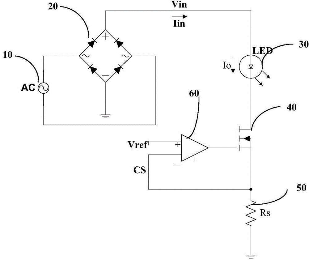
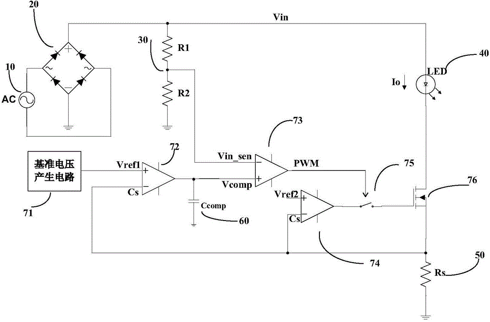
[0021] figure 2 It is a circuit diagram of an LED (Light-Emitting Diode, light-emitting diode) driving circuit provided by a preferred embodiment of the present invention. see figure 2 As shown, a linear switch constant current LED driving circuit for peak current control provided by the present invention includes an AC input power supply 10 for providing an AC supply voltage, a bridge rectifier 20 for converting the AC supply voltage into a DC supply voltage, And LED lamp beads 40 for lighting. The bridge rectifier 20 provides the DC power supply voltage to the LED lamp bead as the working voltage. In addition, the drive circuit also includes a voltage sampling circuit 30 for collecting the input voltage, a sampli...


PUM


Abstract

The invention discloses a linear switching constant-current LED drive circuit for control over peak current, and relates to the field of power source drive circuits. Compared with an existing linear constant-current LED drive circuit, and according to the linear switching constant-current LED drive circuit for control over the peak current, an integrating capacitor is connected to a loop of a drive chip in parallel, and average current passing through an LED lamp bead can be kept to be constant through the integrating constant-current mode; in addition, due to the fact that a loop formed by an operational amplifier, a switching selector and a high-voltage power MOS is added to the loop of the drive chip to limit the peak current passing through the LED bead, useless power consumption of a system can be reduced, working efficiency of the system can be improved, heat produced in the working process of the drive chip is reduced, the required rated current of the LED bead can be effectively reduced, the luminous efficiency of the LED bead is improved, the luminous decay of the LED bead slows down, the service life of the LED bead is prolonged, and cost of the system is reduced.

Description

technical field [0001] The invention relates to the field of power drive circuits, more specifically, to a linear switch constant current LED drive circuit for controlling peak current. Background technique [0002] In the context of global energy conservation and emission reduction, LED lighting, which is green, environmentally friendly and energy-saving, has become more and more popular in the market. Different from the traditional lighting method, it cannot be directly connected to the AC mains power grid, but the AC mains power must be converted into a DC power supply through the drive circuit first, and then driven. LED drive circuits can be divided into two categories: switching power supply type and linear constant current type. Compared with switching power supply type drive, the peripheral circuit of linear constant current type drive is simpler and the cost is lower. Therefore, linear constant current type drive has become a lighting Research focus in the field of...

Claims


Application Information

Patent Timeline
Patent Type & Authority Patents(China)
IPC IPC(8): H05B37/02
Inventor 李进龙晖张利刚
Owner FREMONT MICRO DEVICES SHENZHEN LTD
Why Eureka
Try Eureka