Hybrid single and multimode optical fiber for a home network

A technology of optical fiber and optical fiber core, applied in multi-core optical fiber, multi-layer core/clad optical fiber, clad optical fiber, etc., can solve unresolved problems such as optical power

Active Publication Date: 2014-01-01
德拉卡康泰克私营有限责任公司
View PDF7 Cites 2 Cited by
  • Summary
  • Abstract
  • Description
  • Claims
  • Application Information

AI Technical Summary

Problems solved by technology

Also does not solve the problem of how to r...

Method used


Image

  • Hybrid single and multimode optical fiber for a home network
  • Hybrid single and multimode optical fiber for a home network
  • Hybrid single and multimode optical fiber for a home network

Examples


Embodiment Construction

[0107] In all the drawings of this document, the same elements and steps are indicated by the same numerals.

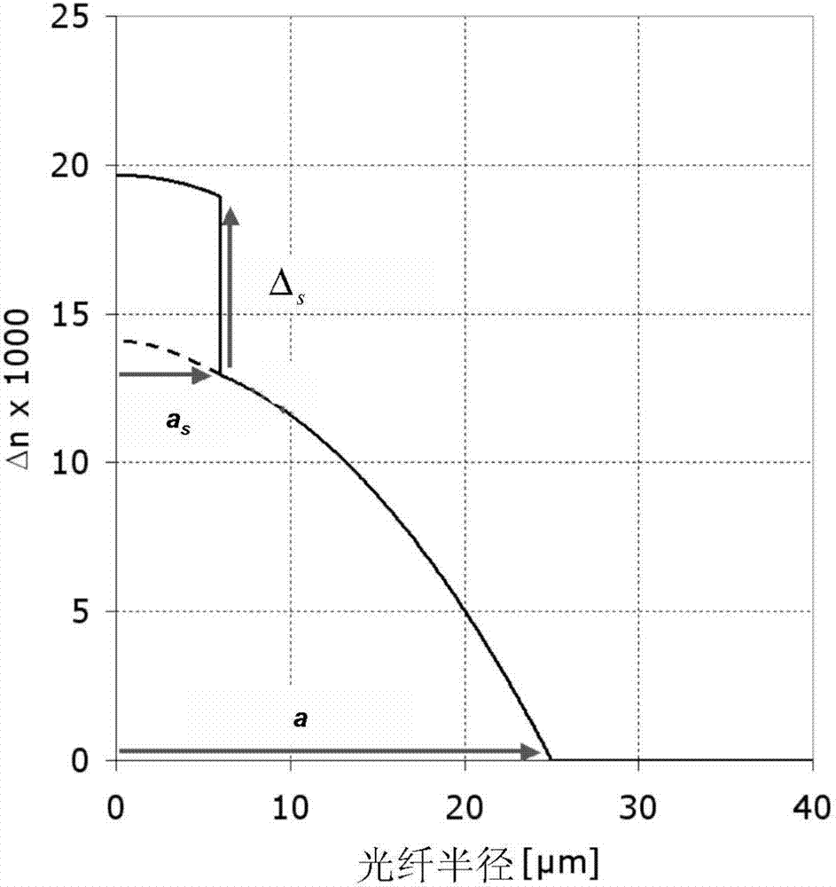
[0108] figure 1 The refractive index profile of the optical fiber according to the first embodiment of the present invention is depicted. It describes the relationship between the refractive index value n and the distance r from the center of the fiber.

[0109] The optical fiber of the present invention is a hybrid optical fiber having a refractive index profile n(r) defined by the following equation:

[0110] n ( r ) = n 0 · 1 - 2 · Δ · ( r ...


PUM

PropertyMeasurementUnit
Radiusaaaaaaaaaa

Abstract

The invention relates to a hybrid optical fiber that includes a multi-segmented optical core exhibiting a refractive graded-index profile typically used to support multimode transmission in which a step-index is added at the center of the optical core, the profile parameters (a s ) and (” s ) of this step-index being tuned so as to provide an optical fiber that transmits both error free multimode optical signals and error free single-mode optical signals. The implementation of such a refractive index profile n(r) of the optical core, as well as the choice of an adequate value of the parameters (a s ) and (” s ) lead to adapt the fundamental mode of the optical fiber such that the optical power coupled into the fundamental mode is maximized at the wavelength of the single-mode transmission, 1550 nm for example, while preserving a relatively reduced modal dispersion at the wavelength of the multimode transmission, 850 nm for example.

Description

1. Technical field [0001] The present invention relates to optical fiber transmission, in particular, to a home network optical fiber supporting single-mode transmission and multi-mode transmission. 2. Background technology [0002] Optical fibers generally consist of a fiber core, which transmits an optical signal, and a fiber cladding, which confines the optical signal within the fiber core. For this, the refractive index n of the core c greater than the refractive index n of the cladding g . A fiber is often characterized by its refractive index profile, which relates the fiber's refractive index (n) to the fiber's radius (r), where: the X-axis shows the distance r from the center of the fiber, and the Y-axis shows the The difference between the refractive index at radius r and the refractive index of the fiber cladding. [0003] Today, there are two main categories of optical fiber: multimode optical fiber and single-mode optical fiber. In multimode fiber, for a giv...

Claims


Application Information

Patent Timeline
IPC IPC(8): G02B6/028G02B6/036
CPCG02B6/03633G02B6/0288G02B6/02042G02B6/0281
Inventor 丹尼斯·莫林皮埃尔·圣索内蒂皮埃尔·希尔德
Owner 德拉卡康泰克私营有限责任公司
Why Eureka
Try Eureka