Multiple cell liquid crystal optical device with coupled electric field control

A liquid crystal optics and electric field technology, applied in optics, optical components, nonlinear optics, etc., can solve problems such as enlargement

Active Publication Date: 2014-01-01
LENSVECTOR
View PDF5 Cites 8 Cited by
  • Summary
  • Abstract
  • Description
  • Claims
  • Application Information

AI Technical Summary

Problems solved by technology

This different effect may be increased due to the difference in the thickness of the liquid crystal layer or the superimposition of the sheet resistance of the two high resistivity layers 19 used to achieve independent refraction of polarization in each direction.

Method used


Image

  • Multiple cell liquid crystal optical device with coupled electric field control
  • Multiple cell liquid crystal optical device with coupled electric field control
  • Multiple cell liquid crystal optical device with coupled electric field control

Examples


Embodiment Construction

[0051] Structure and Operation of Coupling Optics

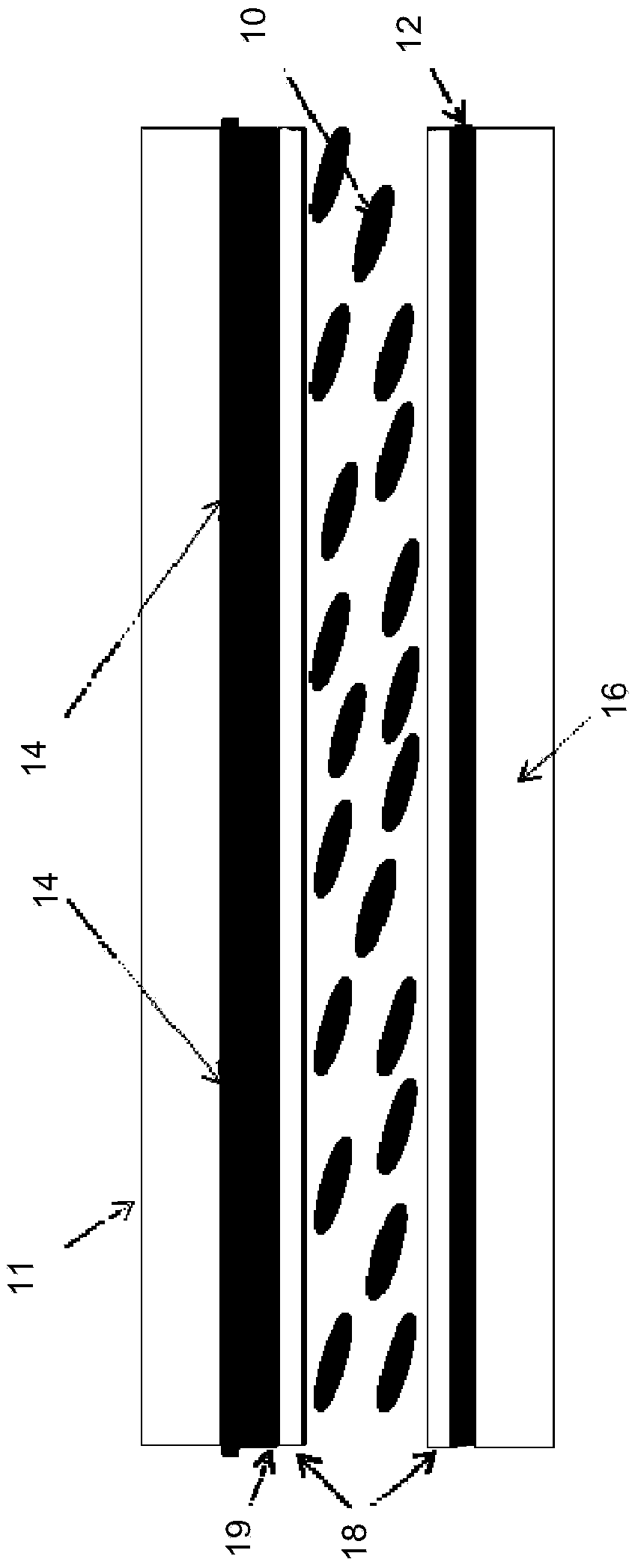
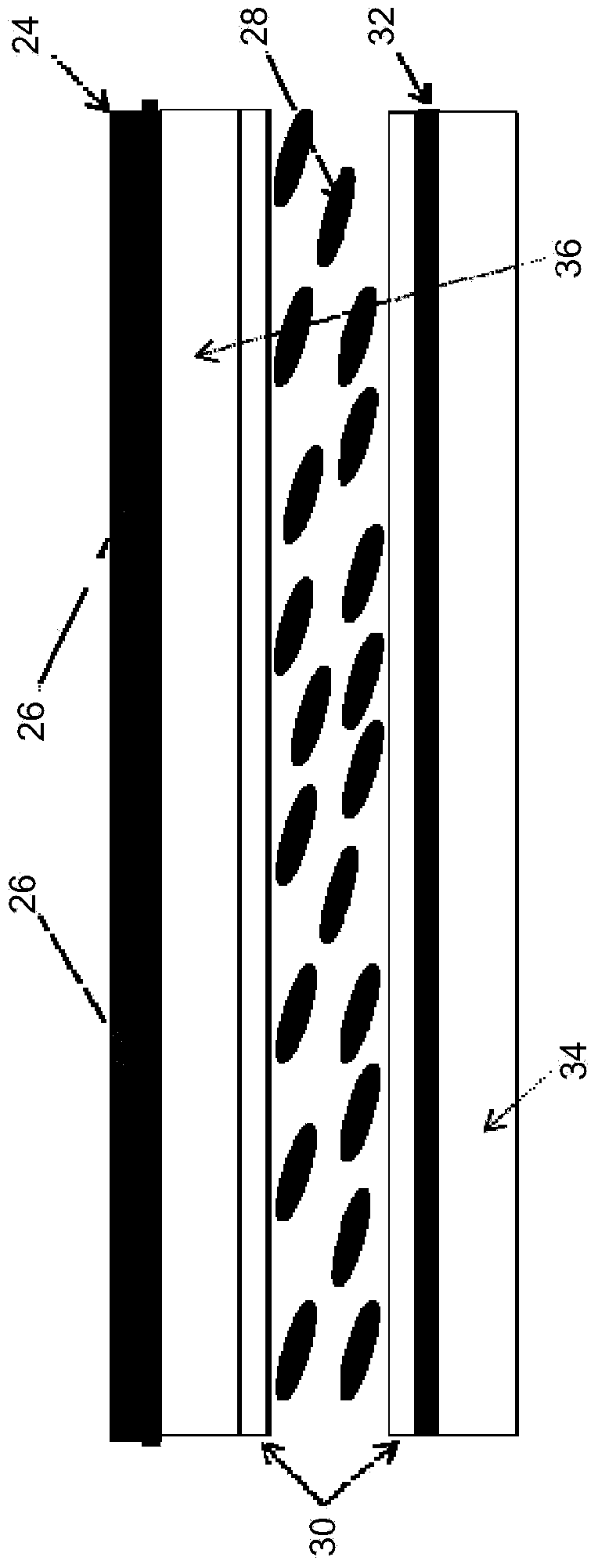
[0052] In commonly assigned International Patent Application PCT / IB2009 / 052658, the contents of which are hereby incorporated by reference, there is disclosed a tunable liquid crystal lens (TLCL) consisting of ring electrodes placed close together on a uniform electrode to produce a desired shape of the electric field. According to the proposed solution, in figure 2 The structure shown in cross-section in , proposes a similar arrangement using a weakly conductive layer (WCL layer) 24 disposed on the outer surface of the layered structure, adjacent to (preferably, in contact with and on top of) the ring electrode 26 . This specific positional setting enables the WCL layer of the lens structure and the WCL layer of the second liquid crystal cell to be coupled together in such a way that the WCL layer of the first cell acts synchronously with the WCL layer of the second cell. Thus, two cells together form a polarization-ind...


PUM

PropertyMeasurementUnit
thicknessaaaaaaaaaa
pore sizeaaaaaaaaaa
diameteraaaaaaaaaa

Abstract

A liquid crystal optical device is provided. The optical device includes a liquid crystal cell controlling optical properties of light passing therethrough and has a liquid crystal layer, a planar electrode located to one side of said liquid crystal layer, an electric field control structure located to the opposite side of the liquid crystal layer, and a wavefront adjustment structure configured to provide optical phase front adjustment. In some embodiments the wavefront adjustment structure is a conductive floating electrode. In other embodiments the wavefront adjustment structure is a weakly conductive structure having spatially variable sheet resistance. In other embodiments, the wavefront adjustment structure a weakly conductive structure having spatially variable sheet resistance having a frequency dependent characteristic.

Description

[0001] related application [0002] The priority document of this application is US provisional application US61 / 424,115, the title of which is "multi-unit liquid crystal optical device for electric field control", and the filing date is December 17, 2010. This application cites the entirety of the priority document. technical field [0003] The invention relates to a liquid crystal optical device, and a control electrode thereof. Background technique [0004] Liquid crystal (LC) lenses and other liquid crystal optical devices are known in the art. A planar structure of liquid crystals is placed in the cell between glass or plastic plates. An electrically variable gradient-index (referred to as GRIN) lens can create a liquid crystal layer with a spatially varying refractive index within the aperture of the device by controlling the relative orientation of the liquid crystal molecules. In this way, a good optical zoom capability can be achieved within a relatively small thi...

Claims


Application Information

Patent Timeline
Patent Type & Authority Applications(China)
IPC IPC(8): G02F1/133G02F1/1343
CPCG02F1/1343G02F1/1347G02F1/133G02F1/134309G02F2001/294G02F1/29G02F2203/06G02F1/294G02B27/64G02B3/0081
Inventor 阿尔门·佐哈拉拜亚恩卡伦·阿萨特里安迪格兰·加尔斯蒂安弗拉底米尔·普雷尼亚科夫阿米尔·图尔克阿拉姆·巴格拉姆亚恩
Owner LENSVECTOR
Why Eureka
Try Eureka