Narrow seam flip bucket structure of high-gradient narrow river valley release structure

A technology for drainage structures and narrow slits, which is applied in the field of sill structures with narrow slits, can solve problems such as unreasonable sill structures, large amount of bank slope protection measures, and bank slope instability, so as to reduce the depth of scour pits and Shore current velocity, extensive guiding significance and promotional significance, good social and economic benefits

Active Publication Date: 2014-01-08
POWERCHINA BEIJING ENG
View PDF4 Cites 8 Cited by
  • Summary
  • Abstract
  • Description
  • Claims
  • Application Information

AI Technical Summary

Problems solved by technology

[0002] Drainage structures in high, steep and narrow valleys generally use straight side walls and narrow slits to deflect energy for energy dissipation. The elevation of the top of the side walls is determined by the highest water surface line plus safety heightening. The height of the side walls is often more than 20m. , the project layout is also difficult to implement, and the concentrated water tongues often rush to the opposite bank, or the spalled water tongues dry and hit the shore, the scour pit is deep, and the water flow velocity on the bank is relatively high
Not only the energy dissipation structure of the discharge structure and the protection measures for the bank slope during the project construction period require a large amount of work and high investment, but also the flood discharge and energy dissipation during the operation period will seriously affect the safety of the hub buildings, which may easily lead to bank slope instability or discharge structures. Energy Dissipating Structural Destruction

Method used


Image

  • Narrow seam flip bucket structure of high-gradient narrow river valley release structure
  • Narrow seam flip bucket structure of high-gradient narrow river valley release structure
  • Narrow seam flip bucket structure of high-gradient narrow river valley release structure

Examples


Embodiment Construction

[0025] In order to make the object, technical solution and advantages of the present invention clearer, the present invention will be further described in detail below in conjunction with the accompanying drawings. It should be understood that the specific embodiments described here are only used to explain the present invention, and are not intended to limit the present invention.

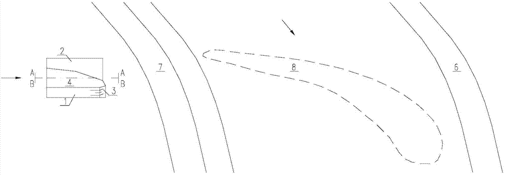
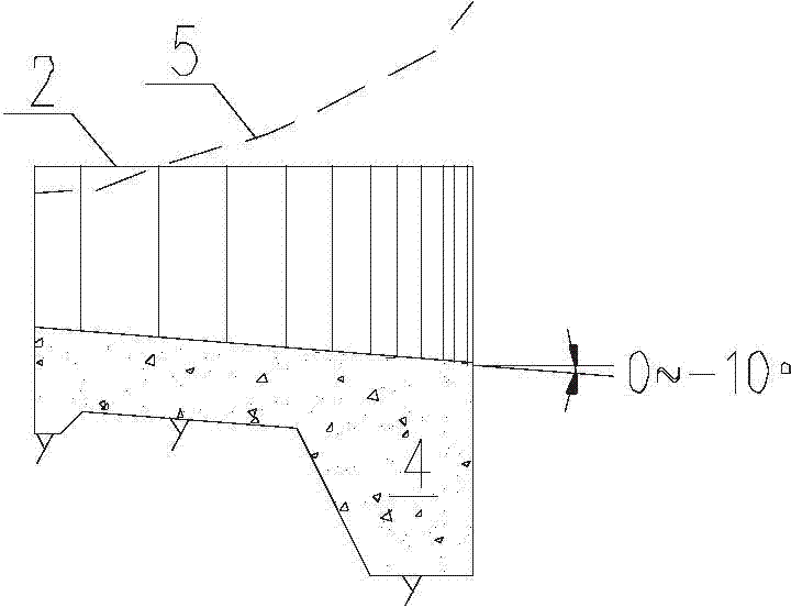
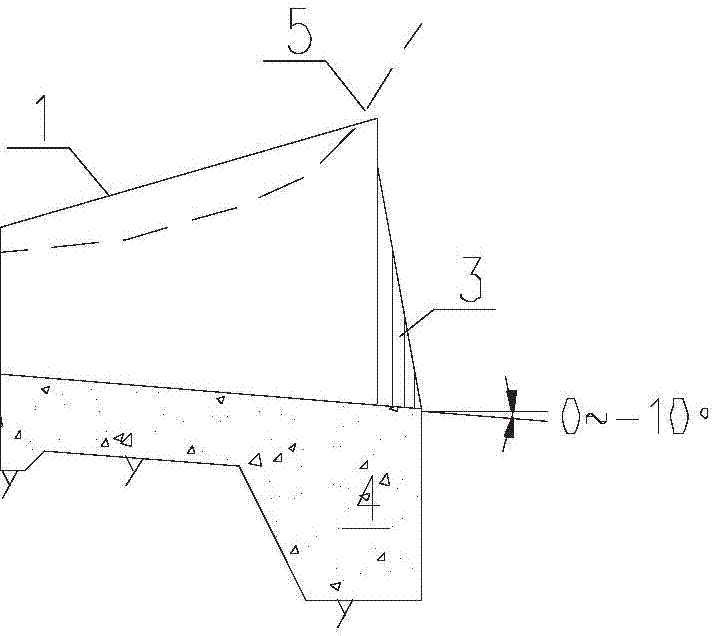
[0026] Such as figure 1 -6. The present invention discloses a narrow seam pick-up structure of a high and steep narrow river valley drainage structure, which is mainly composed of a first side wall, a second side wall, a small corner of the side wall and a bottom plate. The side wall is asymmetrical, and the end of the narrow slit cantilever structure is contracted, and a small corner of the side wall is provided at the same time, and the small corner of the side wall is only arranged on one side; the shrinkage ratio of the narrow slit cantilever is 0.3 to 0.45; the use of water flow The inertia ...


PUM


Abstract

The invention discloses a narrow seam flip bucket structure of a high-gradient narrow river valley release structure. The narrow seam flip bucket structure of the high-gradient narrow river valley release structure comprises a first side wall, a second side wall, small side wall fillets and a bottom board. The tail end of the narrow seam flip bucket structure is contracted and provided with the small side wall fillets. The contraction ratio of the narrow seam flip bucket structure is 0.3 to 0.45. The portion between the first side wall and the second side wall is contracted, so that a nappe disperses and energy is dissipated in the vertical direction and in the direction along a river. The dispersed nappe is prevented from crashing a bank through the small side wall fillets. The falling point range of the nappe is controlled by the narrow seam flip bucket structure to be limited within a river channel center range. According to the narrow seam flip bucket structure of the high-gradient narrow river valley release structure, the characteristic of space dispersing energy dissipation of narrow seam deflecting flow is fully used, the energy dissipation structure of the high-gradient narrow river valley release structure is simplified, the depth of a scoured pit and the bank flow speed are effectively reduced, so that the protection requirements of a bank slope and a riverbed foundation are greatly reduced, influence on the ecological environment and the nodal region bank slope and damage to the ecological environment and the nodal region bank slope are reduced, and the work amount and the engineering investment are reduced.

Description

technical field [0001] The invention relates to the technical field of water discharge and energy dissipation structures for water conservancy and hydropower projects, in particular to a narrow seam pick-up structure for water discharge structures in high, steep and narrow valleys. Background technique [0002] Drainage structures in high, steep and narrow valleys generally use straight side walls and narrow slits to deflect energy for energy dissipation. The elevation of the top of the side walls is determined by the highest water surface line plus safety heightening. The height of the side walls is often more than 20m. , It is also difficult to implement the project layout, and the concentrated water tongues of the deflecting flow often rush to the opposite bank, or the spalled water tongues dry and hit the shore, the scour pit is deep, and the water flow velocity on the bank is relatively high. Not only the energy dissipation structure of the discharge structure and the p...

Claims


Application Information

Patent Timeline
Patent Type & Authority Applications(China)
IPC IPC(8): E02B8/06
Inventor 赵轶邓毅国王敬武秦中平任少辉韩立
Owner POWERCHINA BEIJING ENG
Why Eureka
Try Eureka