

Floor system
A floor and floor technology, which is applied in the field of floor systems, can solve the problems of dust, construction waste, heavy labor intensity of workers, and heavy construction workload, and achieve the effects of low labor intensity, high production efficiency, and reliable quality
- Summary
- Abstract
- Description
- Claims
- Application Information
AI Technical Summary
Problems solved by technology
Method used
Image

Examples
Embodiment 1
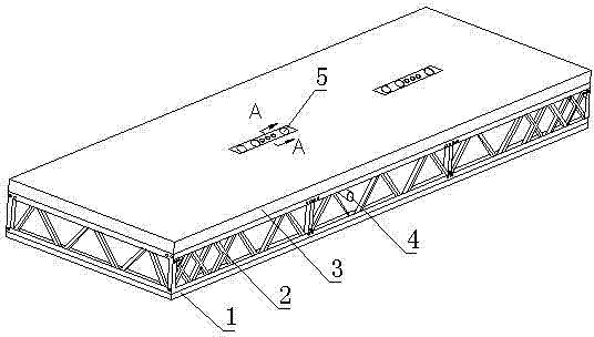
[0034] Such as figure 1 As shown, the floor system includes a floor 2, a floor 3 and a ceiling 1. The upper part of the floor 2 is provided with a floor 3, and the floor 3 is connected and fixed with the floor 2 through concrete. The lower part of the floor 2 is provided with a ceiling 1, and the ceiling 1 is fixed by bolts. At the bottom of floor 2. The ceiling 1 is made of gypsum board, which has the advantages of light weight, low cost, paintability and easy decoration. Of course, the ceiling 1 can also be made of a fireproof board or a prefabricated cement board, and fixed to the bottom of the floor by bolts. This structure of prefabricating the floor 3 and ceiling 1 on the floor 2 changes the traditional way of building for many years. In the past, the interior decoration such as the laying of the floor 3 and ceiling 1 was carried out after the building blanks were all built. The traditional method is time-consuming, complicated to decorate, and cannot be carried out si...
Embodiment 2
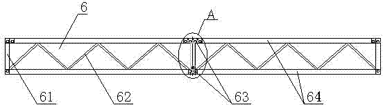
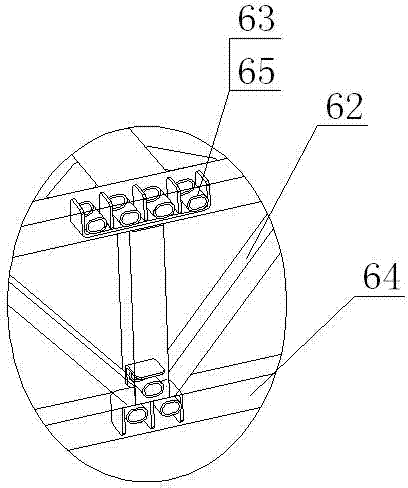
[0041] Such as Figure 6 As shown, the floor system includes a floor 2 and a floor 3. The floor 2 is composed of a rectangular frame composed of steel beams. The upper part of the floor 2 is provided with a floor 3. The floor 3 adopts a steel plate structure and is fixed on the floor 2 by welding. . Because the steel plate and the floor slab 2 can be welded conveniently, compared with tile laying, the construction amount is small, and the construction speed can be effectively improved.
[0042] Such as Figure 4 As shown, the floor system is prefabricated with pipeline systems 7 such as water supply, drainage, air supply, exhaust, power distribution, and garbage. It is designed and manufactured, and fixed inside the floor 2 by means of fixing boxes, fixing plates, hoops, etc. Such as Figure 6 As shown, the pipeline system 7 is provided with a pipeline interface 5 on the floor 3, and the structure of the pipeline interface 5 is the same as that in Embodiment 1. The top, b...
Embodiment 3
[0045] Such as Figure 8 As shown, the floor system is a rectangular frame formed of a plurality of steel beams connected by welding or bolts. Said mounting seat can be a fixed seat 10 or a movable seat 11, which is fixed on the rectangular tube 9 by welding or bolting. The function of these mounts is to connect other building structures, such as frame columns, composite steel beams, walls, etc., so that the floor system and the floor system, columns, beams, and walls can be easily connected with bolts at the construction site. Increase construction speed.
[0046] The rectangular frame of the present invention can also be made of steel beams of other shapes, such as honeycomb beams, I-beams, cross-shaped steels, pipe steels and the like. The connection between steel beams can be welded, or bolted, riveted and other connection methods can be used. The floor system may or may not be prefabricated according to the actual requirements of architectural design; the upper and low...
PUM
 Abstract
Description
Claims
Application Information