Eureka AIR delivers breakthrough ideas for toughest innovation challenges, trusted by R&D personnel around the world.

High-speed and low-speed limiting method of hydraulic speed controller

A hydraulic governor, high and low speed limit technology, applied in the direction of machines/engines, fuel injection control, fuel injection pumps, etc., can solve the problems of narrow limit speed range, can not meet the low speed of diesel engine, etc., achieve simple structure, realize Stable speed regulation effect, high precision and stable speed regulation effect

Active Publication Date: 2014-01-08
CHONGQING HONGJIANG MACHINERY
View PDF4 Cites 0 Cited by
  • Summary
  • Abstract
  • Description
  • Claims
  • Application Information

AI Technical Summary

Problems solved by technology

In the past, the governor could only limit its maximum operating speed in one direction. Generally, it was mainly for the safety of the diesel engine and to avoid the overrun of the diesel engine. Therefore, the maximum speed of the governor was limited, and the low speed was mainly controlled by the diesel engine control system. To adjust, the governor itself has no low speed limit
Or some speed governors can also limit the high and low speeds by adopting the limit method with complex structure, but the speed range of the limit is very narrow. The high limit meets the requirements of the diesel engine, and the low limit cannot meet the requirements of the diesel engine. RPM demand

Method used


Image

  • High-speed and low-speed limiting method of hydraulic speed controller
  • High-speed and low-speed limiting method of hydraulic speed controller
  • High-speed and low-speed limiting method of hydraulic speed controller

Examples


Embodiment Construction

[0017] The present technology will be described below in conjunction with the accompanying drawings.

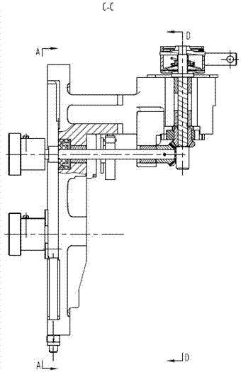
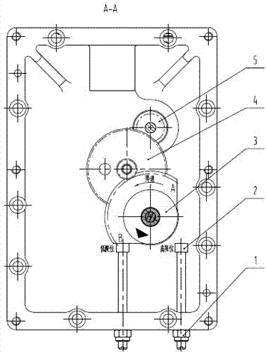
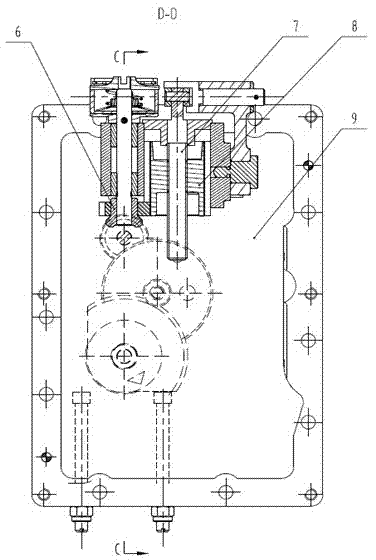
[0018] figure 1 , figure 2 and image 3 , the speed governor mainly includes a lock nut 1, a limit screw 2, a speed indicating gear part 3, an intermediate gear part 4, a speed regulating horizontal shaft 5, a speed regulating gear part 6, a speed regulating screw part 7, a speed regulating gear 8, etc. They are all installed in the governor front cover assembly 9.

[0019] The specific connection structure is as follows: the speed regulating screw part 7 and the speed regulating gear part 6 are connected through the trapezoidal thread, and the up and down movement is converted into the rotation of the speed regulating gear part. The speed regulating gear part 6 is connected by a bevel gear and drives the speed regulating horizontal shaft 5 and the intermediate gear part 4 , and the intermediate gear part 4 is connected and drives the speed indicating gear part 3 . The r...


PUM


Abstract

A high-speed and low-speed limiting method of a hydraulic speed controller comprises a front cover assembly, a speed-controlling screw rod component installed in the front cover assembly, a speed-controlling gear component, a speed-controlling cross rod, a middle gear component and a rotation speed indication gear. The rotation speed indication gear is formed in the mode that a whole circle gear is provided with two mutually-vertical section faces which serve as a highest-rotation-speed limiting face and a lowest-rotation-speed limiting face respectively. Correspondingly, the inside of the front cover assembly of the speed controller is provided with two parallel limiting screw rods, the two limiting screw rods are equal in height, and the highest-rotation-speed limiting face and the lowest-rotation-speed limiting face of the rotation speed indication gear are alternately matched with the two limiting screw rods to achieve the limiting purpose. Compared with a common speed controller, the hydraulic speed controller achieves the effect that the high rotation speed and the low rotation speed can be limited and are adjustable within the rotation speed range, and the speed of a diesel engine can be controlled at high accuracy, so that a stable work rotation speed is available.

Description

technical field [0001] The patent of the invention belongs to the field of diesel engines, and in particular relates to a hydraulic speed governor for fishing boat diesel engines with a power of less than 2000kW. Background technique [0002] With the advancement of science and technology and the continuous improvement of the market's performance requirements for fishing boat diesel engines, modern fishing boat diesel engines are developing in the direction of high performance, high reliability, low noise, low emission, and low fuel consumption. As the key components of fishing boat diesel engines The governor must also adapt to the development of fishing boat diesel engine technology. [0003] For fishing boats, the harsh working environment determines that the diesel engine governor must have good performance and reliability. In the past, the governor could only limit its maximum operating speed in one direction. Generally, it was mainly for the safety of the diesel engin...

Claims


Application Information

Patent Timeline
IPC IPC(8): F02D1/02
Inventor 杨恩志何利黄贵川韩龙徐茂
Owner CHONGQING HONGJIANG MACHINERY
Why Eureka
Eureka Blog
Learn More