Eureka AIR delivers breakthrough ideas for toughest innovation challenges, trusted by R&D personnel around the world.

Backlight module, display device and use method of backlight module

A backlight module and backplane technology, applied in lighting devices, fixed lighting devices, components of lighting devices, etc., can solve problems affecting 3D viewing effects, crosstalk, crosstalk between left and right eye views, etc.

Inactive Publication Date: 2014-01-08
BOE TECH GRP CO LTD +1
View PDF5 Cites 2 Cited by
  • Summary
  • Abstract
  • Description
  • Claims
  • Application Information

AI Technical Summary

Problems solved by technology

However, after one line of image display on the LCD panel is completed, the next LED light bar is lit to display the next line of image. At this time, the image data displayed in this line is still retained. It will illuminate the LCD panel of the next row, and part of the light will also be scattered to the LCD panel of this row, so that the retained image data will continue to be displayed, forming crosstalk
Since the images of the left and right fields of view of the 3D signal are continuously interlaced, the images of the left eye and the right eye are displayed respectively in two adjacent scans, so the viewer can also see the image of the right eye while seeing the left eye image, or Seeing the image for the right eye while seeing the image for the left eye will cause crosstalk between the left and right eye views and affect the 3D viewing effect

Method used


Image

  • Backlight module, display device and use method of backlight module
  • Backlight module, display device and use method of backlight module
  • Backlight module, display device and use method of backlight module

Examples


Embodiment Construction

[0036] The following will clearly and completely describe the technical solutions in the embodiments of the present invention with reference to the accompanying drawings in the embodiments of the present invention. Obviously, the described embodiments are only some, not all, embodiments of the present invention. Based on the embodiments of the present invention, all other embodiments obtained by persons of ordinary skill in the art without making creative efforts belong to the protection scope of the present invention.

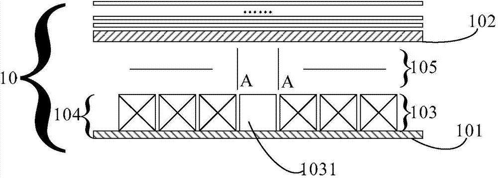
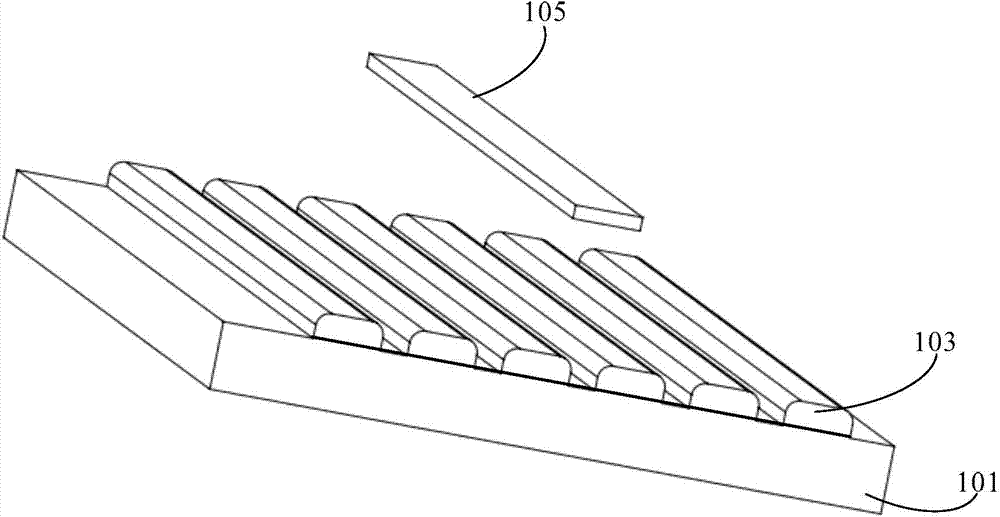
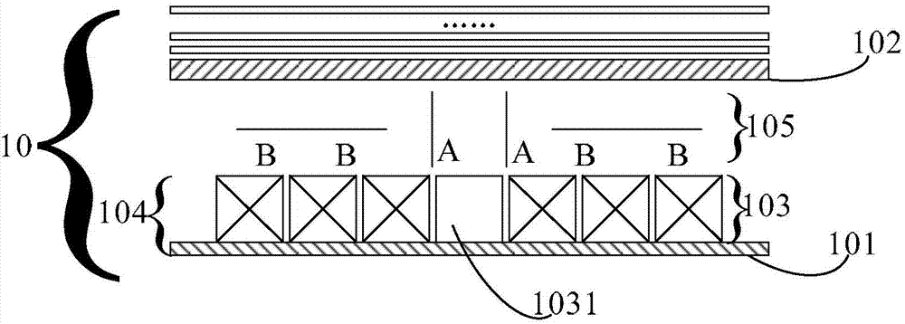
[0037] The embodiment of the present invention provides a backlight module 10, such as figure 1 As shown, it includes a backplane 101 and a diffusion plate 102 , and at least one LED light bar 103 is arranged on the backplane 101 , and the backplane 101 and the at least one LED light bar 103 form a backlight source 104 . The backlight module 10 communicates with the liquid crystal panel ( figure 1 The synchronous scanning of the image data in (not marked) rea...


PUM


Abstract

The embodiment of the invention provides a backlight module, a display device and a use method of the backlight module and relates to the field of liquid crystal display. The backlight module can reduce view crosstalk of the left eye and the right eye and improve the 3D watching effect. The backlight module comprises a back panel and a diffusion plate. At least one LED lamp strip is arranged on the back plane. The backlight module further comprises at least one reflecting sheet and a control unit. The reflecting sheet is located between a backlight source and the diffusion plate. The control unit is used for controlling opening of the reflecting sheet corresponding to the first LED lamp strip when the first LED lamp strip is turned on. The backlight module and the display device are applied to the liquid crystal display field.

Description

technical field [0001] The invention relates to the field of display technology, in particular to a backlight module, a display device and a use method thereof. Background technique [0002] With the rapid development of technology, the TV industry has also experienced technological progress from black and white to color, high definition to 3D (Three Dimensions, three-dimensional), and now people can already enjoy the immersive three-dimensional sense brought by 3D TV. The display principle of 3D TV is to make the images seen by the left and right eyes of the viewer different. In the process of watching, you will see a three-dimensional image. [0003] The currently used 3D liquid crystal display technology adopts progressive backlight scanning technology, that is, the backlight includes at least one LED (Light Emitting Diode, light-emitting diode) light strip, and the at least one LED light strip lights up row by row, and the 3D liquid crystal display The technology divid...

Claims


Application Information

Patent Timeline
IPC IPC(8): F21S8/00F21V7/00H05B37/02G02F1/13357F21Y101/02F21Y115/10H05B44/00
Inventor 赵洪宇王丹李承珉邹斌高振伟郭俊杰吕金库
Owner BOE TECH GRP CO LTD
Why Eureka
Eureka Blog
Learn More