
Fiber-optic gyro temperature drift compensating method based on wavelet analysis and BP (back propagation) neutral network

A technology of BP neural network and fiber optic gyroscope, which is applied to Sagnac effect gyroscope and other directions, can solve the problems such as the influence of model accuracy, and achieve the effect of improving accuracy, improving fitting accuracy, and accurate fitting model of BP neural network.

Active Publication Date: 2014-01-08
BEIHANG UNIV
View PDF3 Cites 21 Cited by
  • Summary
  • Abstract
  • Description
  • Claims
  • Application Information

AI Technical Summary

Problems solved by technology

During the working process of the fiber optic gyro, there are a lot of random noises caused by environmental changes such as quantization noise, angle random walk, and zero bias instability. They are aliased in the gyro signal, and the noise of the samples used in the temperature modeling process will affect the Model accuracy has a big impact

Method used


Image

  • Fiber-optic gyro temperature drift compensating method based on wavelet analysis and BP (back propagation) neutral network
  • Fiber-optic gyro temperature drift compensating method based on wavelet analysis and BP (back propagation) neutral network
  • Fiber-optic gyro temperature drift compensating method based on wavelet analysis and BP (back propagation) neutral network

Examples


Embodiment 1

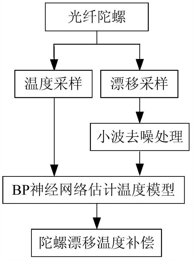
[0032] like figure 1 Shown, the present invention is a kind of fiber optic gyroscope temperature drift compensation method based on wavelet denoising and BP neural network fitting, and its steps are as follows:

[0033] (1) Fix a certain type of fiber optic gyroscope on a horizontal stationary platform, with the sensitive axis pointing to the sky, collect multiple sets of gyroscope signals and temperature outputs started at room temperature, and use the formula (1) to compensate the earth's rotation angular velocity component for the gyroscope output signal Get the gyro zero drift.

[0034] ε=ω ib -ω ie sinL (1)

[0035] In the formula, ε is the gyro drift item; ω ib is the gyro output; ω ie is the angular velocity of the earth's rotation; L is the local latitude.

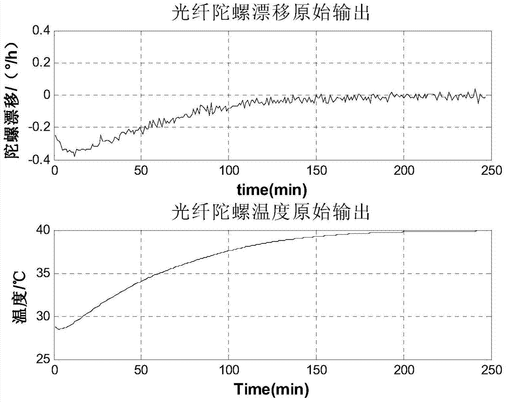
[0036] figure 2 It is one of the groups where the gyro drift and temperature are collected. Depend on figure 2 It can be seen that the standard deviation of the gyro drift is 0.110(°) / h, and it reaches 0...

Embodiment 2

[0049] Utilize the present invention to carry out compensation experiments on the gyro drift collected by a certain fiber optic gyro started multiple times at different times, Figure 7 Compensation effects for 4 of these experiments are shown. Table 2 shows the standard deviation before and after the FOG drift compensation. It can be seen that after the temperature drift is compensated by the present invention, the standard deviation of the optical fiber gyro drift is increased by 6 times.

[0050] Table 2 is the experimental verification effect of the present invention ((°) / h)

[0051]


PUM


Abstract

The invention discloses a fiber-optic gyro temperature drift compensating method based on wavelet analysis and a BP (back propagation) neutral network. The method includes the following steps: utilizing a method of wavelet analysis to analyze and preprocess zero drift data of a fiber-optic gyro, and decomposing to acquire a temperature trend term and a noise term of zero drift of the fiber-optic gyro; utilizing the BP neutral network to fit the temperature trend term to acquire a complex nonlinear relationship between the zero drift of the fiber-optic gyro and temperature; subtracting a drift value acquired by a temperature drift error compensation model by real-time output data of the fiber-optic gyro to realize temperature compensation of the fiber-optic gyro. The fiber-optic gyro temperature drift compensating method completely meets real-time requirements of engineering application and has important significance in performance studying and improving of the fiber-optic gyro under the condition of a constantly-changing temperature environment.

Description

technical field [0001] The invention relates to a compensation method for the drift temperature trend item of an optical fiber gyroscope in the inertial technical field, which is suitable for optical fiber gyroscope testing and system application, and in particular to an optical fiber gyroscope temperature drift compensation method based on wavelet analysis and BP neural network. Background technique [0002] Fiber optic gyroscope is a core component of modern inertial technology. It has the advantages of simple structure, no moving parts, fast startup, low power consumption, impact resistance, wide precision coverage, and large dynamic range. Therefore, it is used in short- and medium-range missiles, ships, It is widely used in aviation, spaceflight, navigation and weapons fields such as anti-submarine weapons, satellites and spacecraft. [0003] Zero random drift is an important index to describe the performance of fiber optic gyro. The zero drift of the fiber optic gyros...

Claims


Application Information

Patent Timeline
IPC IPC(8): G01C19/72
CPCG01C19/72
Inventor 王玮张谦王蕾丁振兴高鹏宇
Owner BEIHANG UNIV
Learn More