
Frequency measurement method based on FPGA

A frequency measurement and frequency technology, which is applied in the field of electronic design automation, can solve the problems of low measurement accuracy, the requirement of maintaining a constant frequency, and the inability to meet the measurement accuracy, etc.

Inactive Publication Date: 2014-01-08
LANGCHAO ELECTRONIC INFORMATION IND CO LTD
View PDF2 Cites 49 Cited by
  • Summary
  • Abstract
  • Description
  • Claims
  • Application Information

AI Technical Summary

Problems solved by technology

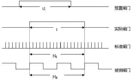
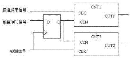
[0005] The purpose of the present invention is to realize in the following manner, adopt a standard reference clock, in unit time (1s) the pulse number of measured signal is counted, It is the frequency of the signal. Since the start and end times of the gate are random for the signal, there will be a quantization error of a pulse period. Further analysis of the measurement accuracy: set the pulse period of the signal to be tested as Tx, and the frequency as Fx , when the measurement time is T=1s, the measurement accuracy is &=Tx / T=1 / Fx; it is known that the measurement accuracy of the direct frequency measurement method is related to the frequency of the signal: when the frequency of the signal to be measured is higher, the measurement accuracy The higher the accuracy is, the lower the measurement accuracy is; the direct frequency measurement method is only suitable for measuring signals with higher frequencies, and cannot meet the requirement that the measurement accuracy in the entire measurement frequency band remain constant. Accuracy problem, using the gating signal and the signal under test to double-control the enabling signal of the counter, which improves the accuracy. When the gating signal is 1, the enabling signal is not 1, and only the rising edge of the measured signal arrives When the enable terminal starts to send a valid signal, the two counters start counting at the same time. When the gating signal becomes 0, the enable signal does not change immediately, but changes when the next rising edge of the measured signal arrives. is 0, the counter stops counting, so the measured error is at most one standard clock cycle. When a 100MHz signal is used as the standard signal, the error is at most 0.01μs; the specific steps are as follows:

Method used


Image

  • Frequency measurement method based on FPGA
  • Frequency measurement method based on FPGA
  • Frequency measurement method based on FPGA

Examples


Embodiment Construction

[0053] The method of the present invention is described in detail below with reference to the accompanying drawings.

[0054] The frequency measurement method with equal precision is developed on the basis of the direct frequency measurement method. Its gate time is not a fixed value, but an integer multiple of the period of the signal under test, that is, it is synchronized with the signal under test. Therefore, it avoids the error of ±1 word generated by counting the signal under test, and achieves a wide range in the entire test frequency band. equal precision measurement. Its frequency measurement principle is as figure 2 .1 shown. During the measurement process, two counters count the standard signal and the measured signal simultaneously. First, the gate opening signal is given (the rising edge of the preset gate), and the counter does not start counting at this time, but the counter actually starts counting when the rising edge of the signal under test arrives. The...


PUM


Abstract

The invention provides a frequency measurement method based on an FPGA. A standard reference clock is adopted to count the number of pulses of a measured signal in a unit time (1s) and the number of the pulses of the measured signal in the unit time (1s) is the frequency of the signal. Due to the fact that the starting moment of a gate and the finishing moment of the gate are random for the signal, a pulse period quantization error can be produced, and measurement accuracy needs to be analyzed further: the pulse period of a signal to be measured is set to be Tx, the frequency is set to be Fx, and when the measuring time T equals to 1s, the measurement accuracy & meets the equation that &=Tx / T=1 / Fx. The fact that measurement accuracy in a direct frequency measurement method is relevant to the frequency of the signal is known, the higher the frequency of the signal to be measured is, the higher the measurement accuracy is, and otherwise, the lower the frequency of the signal to be measured is, the lower the measurement accuracy is. The direct frequency measurement method is only suitable for measurement of the signal at the higher frequency and can not meet the demand that the measurement accuracy remains unchanged in the whole measurement frequency band. In order to overcome the defect of inaccuracy in low-frequency-band measurement, gating signals and the measured signal are used for carrying out dual control on enable signals of the counter, and therefore accuracy is improved.

Description

technical field [0001] The invention relates to the field of electronic design automation (EDA), in particular to an FPGA-based frequency measurement method or a design method of a digital frequency meter. Background technique [0002] With the development of integrated circuit (IC) technology, electronic design automation (EDA) has gradually become an important design method, and has been widely used in many fields such as analog and digital circuit systems. Electronic design automation is a technology to realize the automatic design of electrical systems or electronic products. It is closely related to the development of electronic technology and microelectronics technology. It absorbs most of the latest research results in the field of computer science and uses high-performance computers as work Platform that facilitates engineering development. [0003] A digital frequency meter is a basic measuring instrument. It is widely used in aerospace, electronics, measurement a...

Claims


Application Information

Patent Timeline
IPC IPC(8): G01R23/10
Inventor 符云越
Owner LANGCHAO ELECTRONIC INFORMATION IND CO LTD
Learn More