LED (Light Emitting Diode) drive circuit
A technology of LED driving and driving current, applied in the direction of lamp circuit layout, electric light source, electrical components, etc., can solve the problems of low LED utilization rate, affecting the service life of the system, and uneven LED utilization rate.
- Summary
- Abstract
- Description
- Claims
- Application Information
AI Technical Summary
Problems solved by technology
Method used
Image
Examples
Embodiment 1
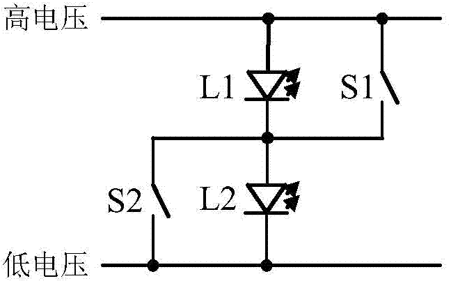
[0125] In this example, if image 3 As shown, the LED array includes two LEDs L1, L2 and two switches S1, S2, the two LEDs are respectively the first LED L1 and the second LED L2, and the cathode of the first LED L1 is connected to the second LED L1. The anodes of the two LED L2 are connected, and the anode of the first LED L1 and the cathode of the second LED L2 are respectively connected to the output voltage v o The high and low voltage terminals are connected, the two switches are the first switch S1 and the second switch S2 respectively, and the first switch S1 and the second switch S2 are respectively connected in parallel with the first LED L1 and the second LED L2 , the LED structure control circuit is used to control the on-off of the two switches S1 and S2.
[0126] In this embodiment, the first voltage value is the minimum voltage level, the third voltage value is the maximum voltage level, the first current value is the maximum current, and the third current value...
Embodiment 2
[0134] Compared with the technical solution in the first embodiment, this embodiment is different in steps 4 and 5 in the LED array and its driving method, and the rest of the technical features are the same as those in the first embodiment, which will not be repeated here.
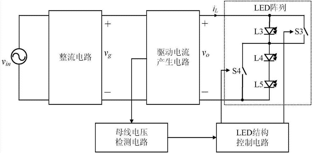
[0135] In this example, if Figure 4 and Figure 5 As shown, the LED array includes three LEDs L3, L4, L5 and two switches S3, S4, the three LEDs are respectively the third LED L3, the fourth LED L4 and the fifth LED L5, the third The cathode of the LED L3 is connected to the anode of the fourth LED L4, the anode of the fourth LED L4 is connected to the anode of the fifth LED L5, the anode of the third LED L3 is connected to the anode of the fifth LED L5 Negative poles are respectively connected to the output voltage v o The high and low voltage terminals are connected, the two switches are respectively the third switch S3 and the fourth switch S4, the third switch S3 is connected in parallel with the t...
Embodiment 3
[0143] Compared with the technical solutions in the previous two embodiments, this embodiment is different in steps 4 and 5 in the LED array and its driving method, and the rest of the technical features are the same as those in the previous two embodiments, so it will not be repeated here. repeat.
[0144] In this example, if Image 6 As shown, the LED array includes three LEDs L6, L7, L8 and four switches S5, S6, S7, S8, the three LEDs are respectively the sixth LED L6, the seventh LED L7 and the eighth LED L8, The negative pole of the sixth LED L6 is connected to the positive pole of the seventh LED L7, the negative pole of the seventh LED L7 is connected to the positive pole of the eighth LED L8, and the positive pole of the sixth LED L6 is connected to the positive pole of the eighth LED L8. The negative poles of the eight LEDs L8 are respectively connected to the output voltage v o The high and low voltage terminals are connected, and the four switches include the fift...
PUM
 Abstract
Description
Claims
Application Information
 - R&D
- Intellectual Property
- Life Sciences
- Materials
- Tech Scout
- Unparalleled Data Quality
- Higher Quality Content
- 60% Fewer Hallucinations
Browse by: Latest US Patents, China's latest patents, Technical Efficacy Thesaurus, Application Domain, Technology Topic, Popular Technical Reports.
© 2025 PatSnap. All rights reserved.Legal|Privacy policy|Modern Slavery Act Transparency Statement|Sitemap|About US| Contact US: help@patsnap.com


