Method for monitoring rammed point soil stabilization state vibration in real time

A soil reinforcement and real-time monitoring technology, which is applied in soil protection, on-site foundation soil survey, construction, etc., can solve the problems of rough reflection of foundation reinforcement status, collapsibility coefficient to be studied, time-consuming and labor-intensive problems, etc.

Active Publication Date: 2014-01-15
CHINA UNIV OF GEOSCIENCES (BEIJING) +1
View PDF6 Cites 15 Cited by
  • Summary
  • Abstract
  • Description
  • Claims
  • Application Information

AI Technical Summary

Problems solved by technology

This monitoring method has at least the following problems: first, the efficiency is low, and the hammer needs to be stopped and waited for each tamping measurement, which affects the construction speed; second, the measurement index error is large. The position in the rammed pit is somewhat arbitrary, and the measurement error of the rammed settlement is relatively large, which reflects roughly the state of foundation reinforcement. The relationship between the degree of compaction and the collapsibility coefficient needs to be studied
[0014] To sum up, at present, during the dynamic compaction construction process, the method for monitoring the soil reinforcement state at the compaction point is single, with low efficiency, poor accuracy, time-consuming and labor-intensive, especially in the case of major projects with tight schedules and high quality requirements. big limitations

Method used


Image

  • Method for monitoring rammed point soil stabilization state vibration in real time
  • Method for monitoring rammed point soil stabilization state vibration in real time
  • Method for monitoring rammed point soil stabilization state vibration in real time

Examples


Embodiment Construction

[0057] The present invention will be described in detail below in conjunction with the implementations shown in the drawings, but it should be noted that these implementations are not limitations of the present invention, and those of ordinary skill in the art based on the functions, methods, or structural changes made by these implementations Equivalent transformations or substitutions all fall within the protection scope of the present invention.

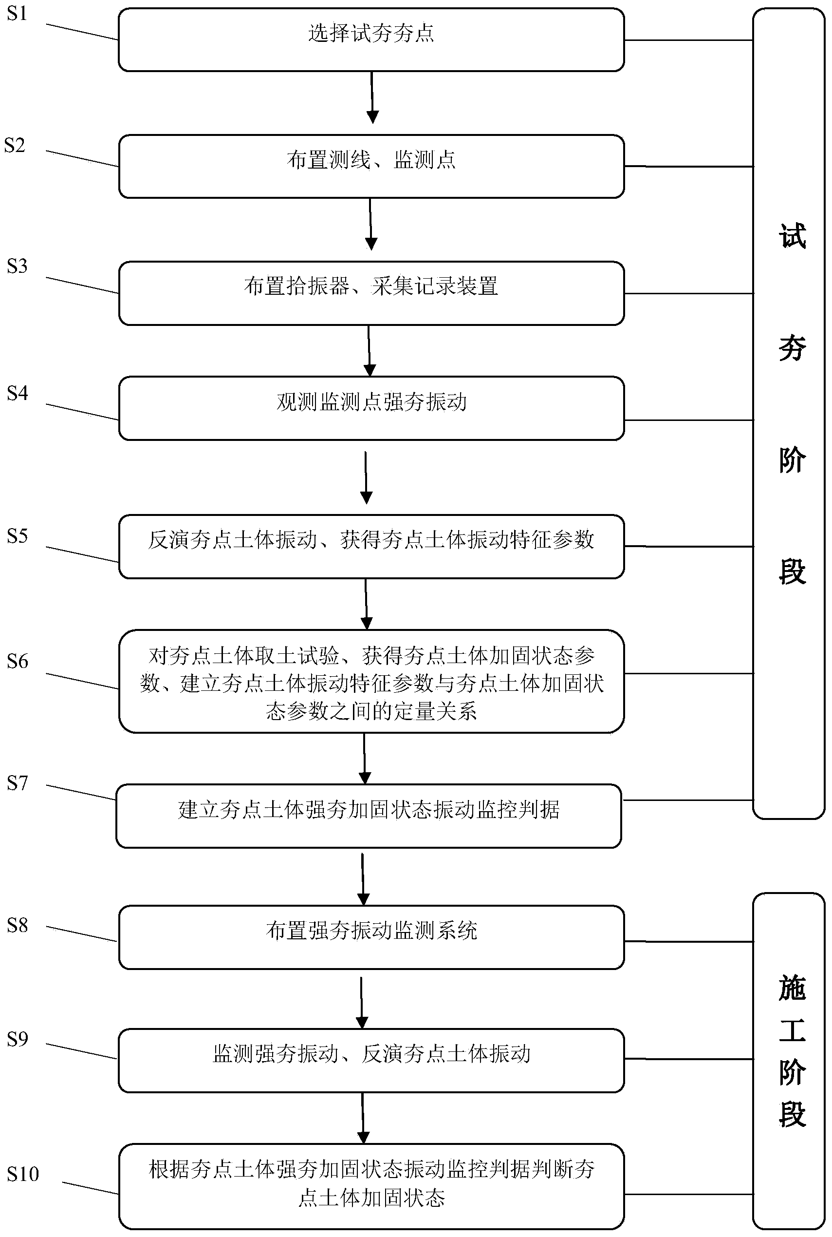
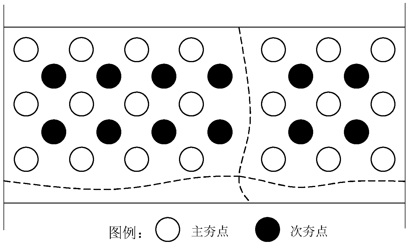
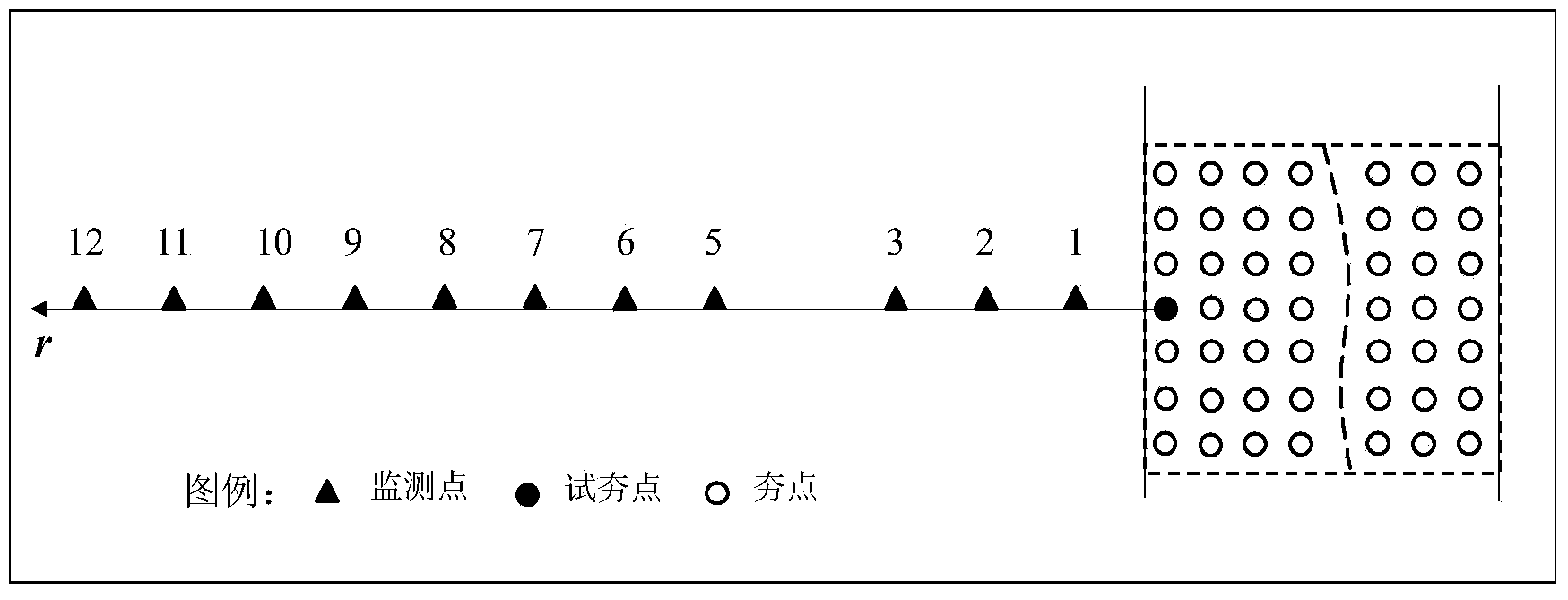
[0058] Such as Figure 1 to Figure 3 as shown, figure 1 It is a flow chart of a method for real-time monitoring of the vibration of the tamping point soil reinforcement state of the present invention; figure 2 It is a schematic diagram of plane layout of tamping points in the test tamping stage of a method for real-time monitoring of vibration of tamping point soil reinforcement state of the present invention; image 3 It is a schematic plan layout diagram of a dynamic tamping vibration monitoring system during the dynamic tamp...


PUM


Abstract

The invention discloses a method for monitoring rammed point soil stabilization state vibration in real time. The method comprises the two steps of trial ramming and construction. According to the step of trial ramming, a trial rammed point is selected, a measurement line and a monitoring point are arranged, a vibration pickup and a collecting and recording device are arranged, forced-ramming vibration of the monitoring point is observed, back analysis is carried out on the rammed point soil vibration, characteristic parameters of the rammed point soil vibration are obtained, soil of the rammed point soil is extracted to be tested, rammed point soil stabilization state parameters are obtained, a quantitative relation between the characteristic parameters of the rammed point soil vibration and the rammed point soil stabilization state parameters is set, and monitoring criteria of the rammed point soil forced-ramming stabilization state vibration are set. According to the step of construction, a forced-ramming vibration monitoring system is arranged, forced-ramming vibration is monitored, back analysis is carried out on the rammed point soil vibration, and the rammed point soil stabilization state is judged according to the monitoring criteria of the rammed point soil heave-ramming stabilization state vibration. The method for monitoring the rammed point soil stabilization state vibration in real time can improve efficiency and accuracy for monitoring the rammed point soil stabilization state, and lower the construction cost.

Description

technical field [0001] The invention relates to the field of foundation reinforcement, in particular to a method for real-time monitoring of vibration in the state of soil reinforcement at ramming points. Background technique [0002] Dynamic consolidation, English called Dynamic consolidation, that is, dynamic consolidation, was first created by French engineer Menard in 1969, and was introduced in detail through literature in 1975. When strengthening the foundation with dynamic ramming, hoist the 8-30t (about 80-300kN) rammer to the air of 6-40m, and then let the rammer fall freely to hit the ground, generating a huge stress wave in the soil and reorganizing the soil structure Compaction, so as to improve the bearing capacity of the foundation and reduce the compression deformation of the foundation. [0003] The construction of the dynamic compaction method is simple and easy, the reinforcement effect is good, the material is saved, the application range is wide, and the...

Claims


Application Information

Patent Timeline
Patent Type & Authority Applications(China)
IPC IPC(8): E02D3/054E02D1/00
Inventor 孙进忠刘治峰梁向前吕兴波李高靳中磊熊峰马建国邵安阳娄素丽肖庭庭贾荣刚
Owner CHINA UNIV OF GEOSCIENCES (BEIJING)
Why Eureka
Try Eureka