
Wall-mounting-type vertical coal bunker without coal feeder chamber

A coal feeder and wall-mounted technology, which is applied in the field of wall-mounted vertical coal bunkers, can solve the problems of reduced stability of the overall load-bearing structure of the coal feeder chamber, unsafe and efficient use of coal bunkers, and inward movement of both side walls or columns. , to achieve the effects of reducing construction and maintenance costs, wide applicability, and easy maintenance

Inactive Publication Date: 2014-01-15
CHINA UNIV OF MINING & TECH
View PDF5 Cites 2 Cited by
  • Summary
  • Abstract
  • Description
  • Claims
  • Application Information

AI Technical Summary

Problems solved by technology

The two sides of the common coal feeder chamber are high-strength concrete side walls or concrete columns. When the load of the coal bunker acts on the two sides of concrete side walls or concrete columns, the compression molding effect of the two sides of concrete side walls or concrete columns Under the action of , far-field stress and water, the surrounding rock continues to squeeze and flow into the chamber, which causes the walls or columns on both sides to move inward and tilt, and finally the stability of the coal feeder chamber due to its overall load-bearing structure decreases sharply. It is difficult to continue to effectively carry
The existing technology is to artificially increase the support strength of the coal feeder chamber, the strength of the surrounding rock, and take effective drainage measures, but none of them can fundamentally solve the problem that the surrounding rock of the coal feeder chamber is easily affected by water, pressure, etc. Influenced by factors, especially the problem that the coal bunker cannot be used safely and efficiently due to the strong floor drum of the coal feeder chamber

Method used


Image

  • Wall-mounting-type vertical coal bunker without coal feeder chamber
  • Wall-mounting-type vertical coal bunker without coal feeder chamber
  • Wall-mounting-type vertical coal bunker without coal feeder chamber

Examples


Embodiment Construction

[0022] An embodiment of the present invention will be further described below in conjunction with accompanying drawing:

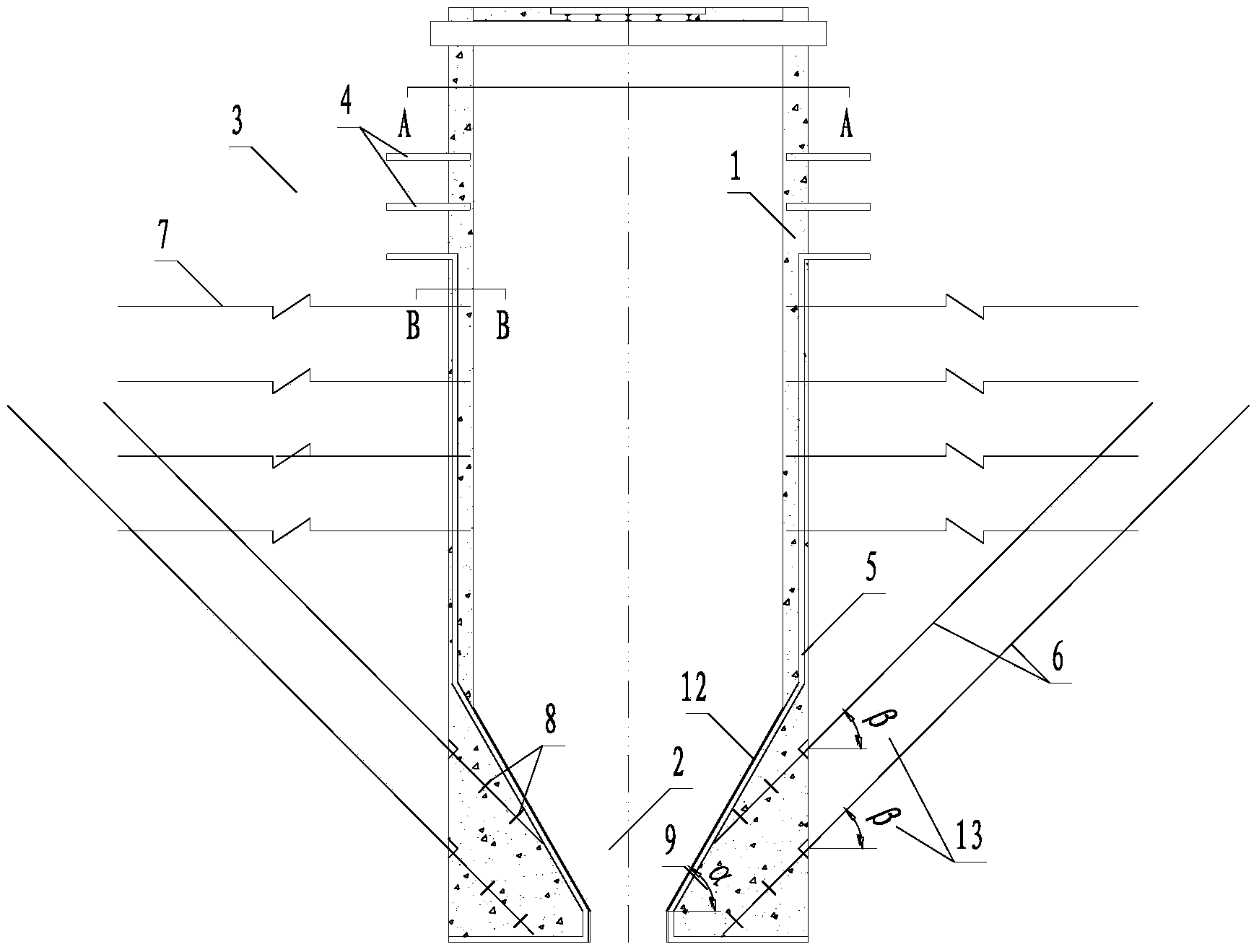
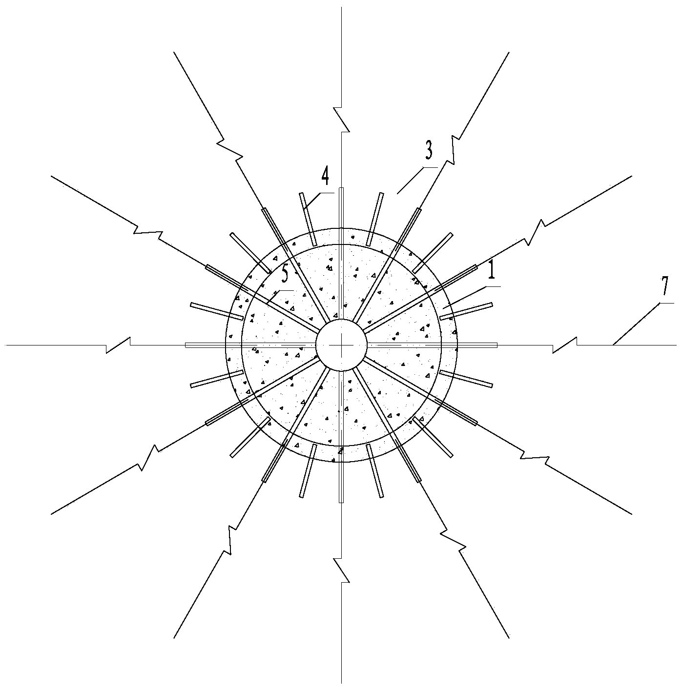
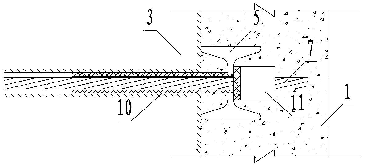
[0023] Such as figure 1 , figure 2 As shown, the wall-mounted vertical coal bunker without coal feeder chamber of the present invention comprises a cylindrical reinforced concrete silo body 1, a frustum-shaped constriction 2 at the bottom of the cylindrical reinforced concrete silo body 1, and a frustum-shaped constriction slope The angle α(9) with the horizontal direction is set according to the repose angle of coal not less than 55°. The inclined surface of the frustum-shaped constriction 2 is laid with an impact-resistant and wear-resistant lining 12 made of inorganic composite building materials. Along the outer wall of the cylindrical reinforced concrete silo 1 and the inner wall of the conical constriction 2, a plurality of I-shaped steel silo brackets 5 are arranged at intervals, and the I-shaped steel silo in the cylindrical reinforced concrete s...


PUM

PropertyMeasurementUnit
Lengthaaaaaaaaaa

Abstract

The invention discloses a wall-mounting-type vertical coal bunker without a coal feeder chamber. The wall-mounting-type upright coal bunker comprises a vertical cylindrical reinforced concrete bunker body and a cone-frustum-shaped necking opening in the lower portion of the bunker body. An H-beam steel joist and an H-beam steel bunker body bracket which play a role in load bearing are embedded inside bunker wall rock and used for supporting the reinforced concrete bunker body. A load-bearing anchor rope which is embedded into the reinforced concrete bunker body and inserted into the bunker wall rock is arranged at the position, arranged inside the cone-frustum-shaped necking opening, of the H-beam steel bunker body bracket. A tray and a locking tool are arranged at the position, located inside the reinforced concrete bunker body, of the load-bearing anchor rope, wherein the tray plays a role in load bearing, and the locking tool is used for fixing the tray. The loading-bearing anchor rope, the H-beam steel bunker body bracket, an H-beam steel bunker body bracket fixed anchor rope and an H-beam steel bracket jointly support the reinforced concrete bunker body and coal inside the bunker body. According to the wall-mounting-type vertical coal bunker, the chamber special for a coal feeder of an existing coal bunker is eliminated, and the difficult problem that due to the fact that the surrounding rock of the coal feeder chamber is easily affected by factors like water and pressure, and especially due to the intense heaving floor of the coal feeder chamber, the coal bunker can not be safely and efficiently used is solved.

Description

technical field [0001] The invention relates to an upright coal bunker at the bottom of a coal mine, in particular to a wall-mounted upright coal bunker without a chamber for a coal feeder, which is suitable for the bottom drum of a roadway below the coal bunker. Background technique [0002] A special coal feeder chamber is built in the lower part of the vertical coal bunker under the existing coal mine, and this chamber bears the total weight of the coal in the coal bunker, the concrete bin body and the coal feeder. Therefore, the strength and stability of the coal feeder chamber is the key to the normal and safe use of the coal bunker. The two sides of the common coal feeder chamber are high-strength concrete side walls or concrete columns. When the load of the coal bunker acts on the two sides of concrete side walls or concrete columns, the compression molding effect of the two sides of concrete side walls or concrete columns Under the action of , far-field stress and w...

Claims


Application Information

Patent Timeline
IPC IPC(8): E21F13/00E21D21/00
Inventor 谢文兵臧龙王其洲荆升国
Owner CHINA UNIV OF MINING & TECH
Learn More