Secondary air injection system

A secondary air and injection system technology, applied in the direction of exhaust devices, mechanical equipment, engine components, etc., can solve the problems of weight and volume increase, achieve the effect of improving low-speed performance and high-speed performance, and reducing the amount of precious metals

Inactive Publication Date: 2014-01-15
HYUNDAI MOTOR CO LTD
View PDF1 Cites 11 Cited by
  • Summary
  • Abstract
  • Description
  • Claims
  • Application Information

AI Technical Summary

Problems solved by technology

[0010] However, in order to achieve this purpose, since it is especially necessary to provide a secondary air pump, the weight and volume increase

Method used


Image

  • Secondary air injection system
  • Secondary air injection system
  • Secondary air injection system

Examples


Embodiment Construction

[0024] Reference will now be made in detail to various embodiments of the invention, examples of which are illustrated in the accompanying drawings and described below. While the invention will be described in conjunction with exemplary embodiments, it will be appreciated that present description is not intended to limit the invention to those exemplary embodiments. On the contrary, the invention is intended to cover not only the exemplary embodiments but also various alternatives, modifications, equivalents and alternatives, modifications, equivalents and alternatives, which may be included within the spirit and scope of the invention as defined by the appended claims. Other specific embodiments.

[0025] Like reference numerals refer to like elements throughout the specification.

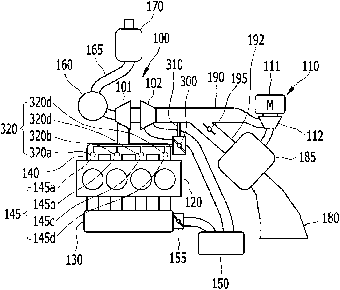
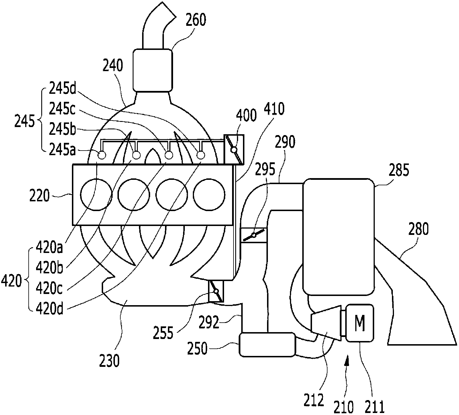
[0026] figure 2 and 3 are diagrams showing secondary air injection systems according to various embodiments of the present invention.

[0027] Various implementation aspects of the invention ...


PUM


Abstract

The invention discloses a secondary air injection system. The secondary air injection system supplying some of air introduced into an intake manifold to an exhaust manifold may include: an electric supercharger compressing air introduced through an air duct; throttle valves installed at an upstream of the intake manifold and controlling the amount of air introduced into the intake manifold by controlling the amount of air passing through the electric supercharger; secondary air valves installed on branching paths branched from intake, lines that link the electric supercharger and the throttle vales and controlling the amount of air for secondary air injection; and an injector that post-combusts exhaust gas discharged from an engine by injecting secondary air passing through the secondary air valve to a runner of the manifold.

Description

[0001] Cross References to Related Applications [0002] This application claims priority from Korean Patent Application No. 10-2012-0064353 filed on June 15, 2012, the entire contents of which are hereby incorporated by reference for all purposes. technical field [0003] The present invention relates to secondary air injection systems. More particularly, the present invention relates to a secondary air injection system that supplies secondary air to exhaust gas by branching air introduced into an intake manifold. Background technique [0004] In a conventional vehicle intake / exhaust system, intake air is supplied to an engine through an intake manifold and the supplied intake air is combusted in the engine to be exhausted to the outside through an exhaust manifold. [0005] In this case, the exhaust air includes vapors (H2O), nitrogen (N2), carbon dioxide gas (CO2), etc. that are not harmful to humans, but also toxic materials such as carbon monoxide (CO), hydrocarbons (H...

Claims


Application Information

Patent Timeline
Patent Type & Authority Applications(China)
IPC IPC(8): F02B37/12F01N3/30
CPCF01N3/222F01N3/34F02B37/04F02B37/168F02B39/10Y02T10/12F01N3/05F01N3/30F02B33/34F02D9/10F02B29/04
Inventor 韩东熙任爀韩胜国朴哲镐全在英崔在爀朴钟一
Owner HYUNDAI MOTOR CO LTD
Why Eureka
Try Eureka