a steam generator

A technology of steam generator and steam-water separator, which is applied in steam generation method using heat carrier, chemical instrument and method, liquid degassing, etc., can solve the problems of poor management, large water capacity, waste of steam, etc. The effect of high coefficient, small water capacity and fast steam production

Active Publication Date: 2016-02-10
ZHEJIANG UNIPOWER BOILER CO LTD
View PDF7 Cites 5 Cited by
  • Summary
  • Abstract
  • Description
  • Claims
  • Application Information

AI Technical Summary

Problems solved by technology

The current steam equipment is mainly drum-type boilers. The main feature of this boiler is its large water capacity. It takes a long time from starting the boiler to supplying steam to the equipment. Poor management and potential explosion hazards
After the equipment stops, a large amount of high-temperature water and steam in the boiler are wasted; the saturated water temperature in the boiler determines that the exhaust gas temperature must be higher than the saturated steam temperature, and the energy efficiency is not high

Method used


Image

  • a steam generator
  • a steam generator
  • a steam generator

Examples


Embodiment 1

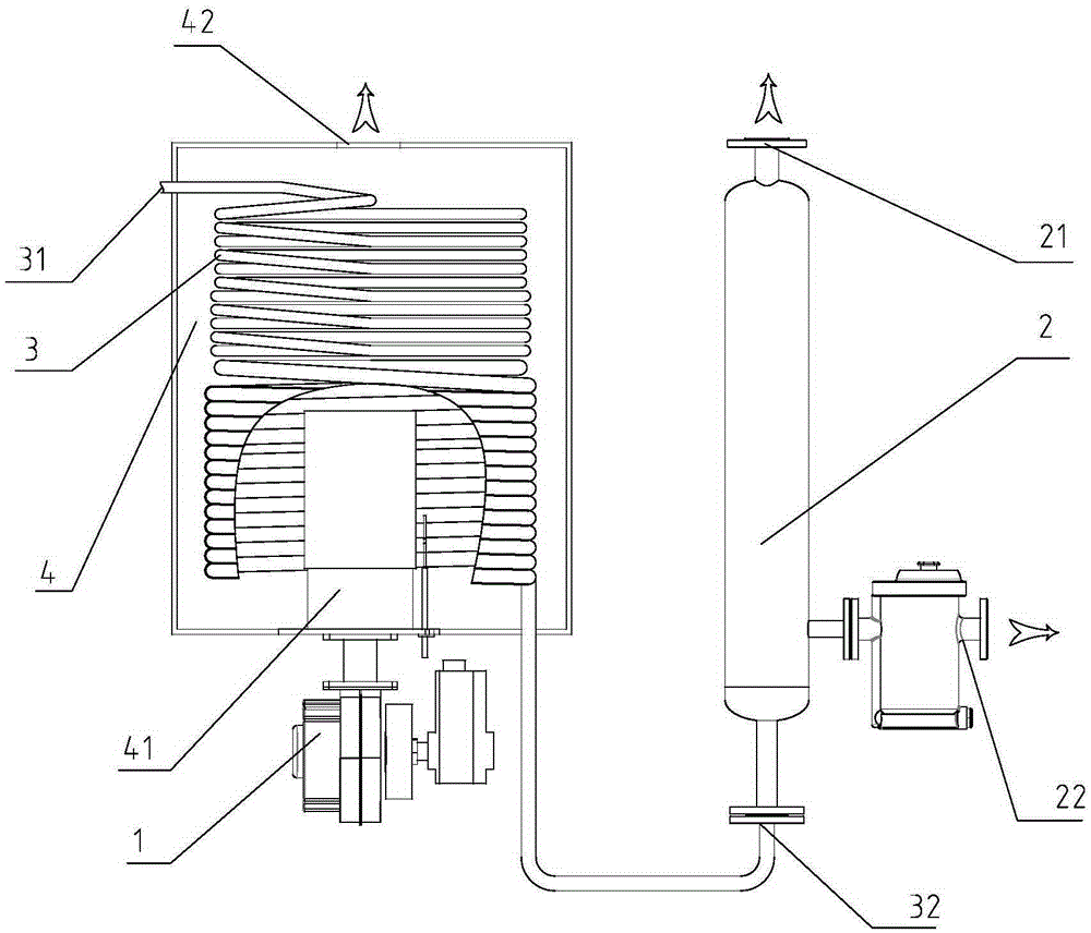
[0021] refer to figure 1 , the steam generator shown includes a coil 3, a burner 1, a steam-water separator 2 and a water supply source, the coil 3 is connected between the steam-water separator 2 and the water supply source, the burner 1 is provided with a furnace 4, and the disk The pipe 3 is arranged in the furnace 4 , and the furnace 4 is provided with a smoke inlet pipe 41 extending into the coil 3 . After the flue gas exchanges heat with the burner 1, it enters the furnace 4 through the smoke inlet pipe 41 to exchange heat with the coil 3, and the deoxygenated water from the water supply source enters the coil 3 through the water pump, and the deoxygenated water flows in the coil 3 During the process, it is heated by the flue gas to form a mixture of steam and water. The steam-water separator 2 separates the two, and the steam is sent from the steam outlet 21 at the upper end of the steam-water separator 2 to the steam-consuming equipment, and the high-temperature water ...

Embodiment 2

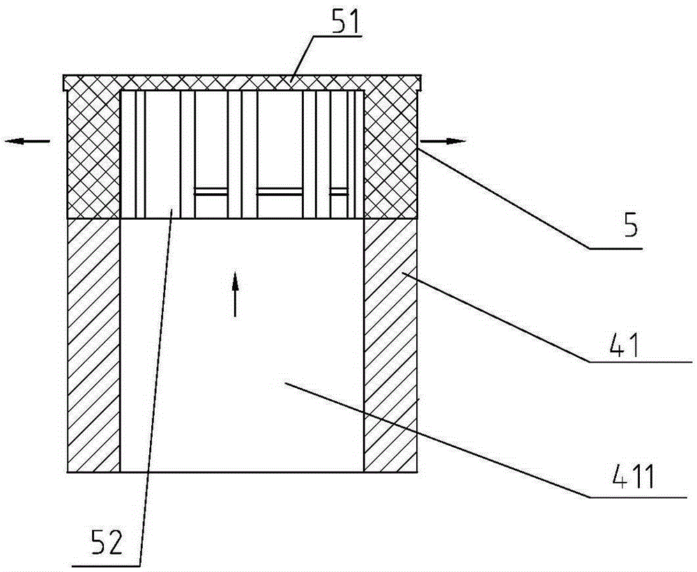
[0025] refer to figure 1 , figure 2 and image 3 , on the basis of Embodiment 1, a spoiler 5 is provided in the furnace 4, and the spoiler 5 is opposite to the smoke inlet 411 of the smoke inlet pipe 41. After the high-temperature flue gas enters the furnace 4, the flow of the flue gas tends to the upper end The direction of the smoke outlet 42 leads to poor utilization of the heat energy of the smoke. The smoke inlet 411 of the smoke inlet pipe is blocked by the spoiler 5. The blocking effect of the spoiler 5 can slow down the speed of the smoke and make the smoke The gas is discharged from the surroundings to ensure that the flue gas is in full contact with the coil 3 and improve the utilization rate of heat energy.

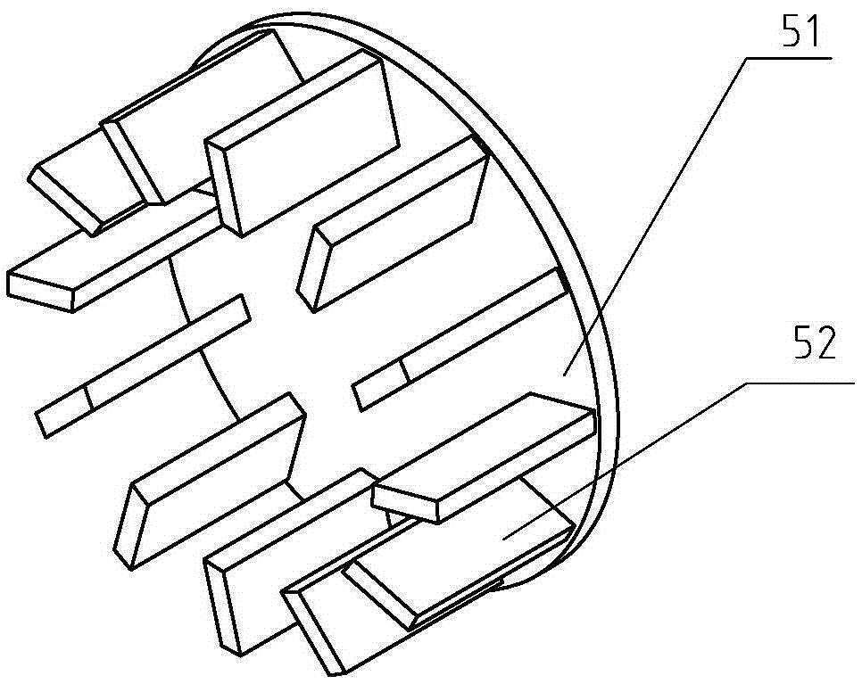
[0026] The spoiler 5 in this embodiment includes a smoke baffle 51 arranged above the smoke inlet pipe 41, and the surface of the smoke baffle 51 opposite to the smoke inlet 411 is surrounded by a disturbance flow sheet 52, and the flow baffle 52 passes thro...


PUM


Abstract

The invention discloses a steam generator, and relates to the field of steam equipment. The technical problems that in the prior art, a drum type boiler is started slowly when producing steam, is large in heat waste and has explosion risks are solved. The steam generator comprises a coil pipe, a combustor, a steam separator and a feed water source, wherein the coil pipe is connected between the steam separator and the feed water source, a combustion chamber is formed in the combustor, the coil pipe is arranged in the combustion chamber, and a smoke inlet pipe is arranged on the combustion chamber and extends into the coil pipe. The air-fuel ratio can be accurately controlled through the combustor, and after radiation heat transfer, smoke gas flows through the outer side of the coil pipe in the combustion chamber to exchange heat with fluid in the coil pipe; in comparison with boiler heating, the coil pipe is small in size and water capacity and free of the explosion risks, the coefficient of heat transfer of the coil pipe is high, heating loads per unit are large, steam generating speed is high, smoke exhaust temperature is low, and the use ratio of energy is high.

Description

【Technical field】 [0001] The present invention relates to an apparatus for converting water into steam. 【Background technique】 [0002] Steam is one of the main sources of heat and power in industry. A steam generator is a device that heats water to a certain parameter and produces high-temperature steam. The current steam equipment is mainly drum-type boilers. The main feature of this boiler is its large water capacity. It takes a long time from starting the boiler to supplying steam to the equipment. Poor management and potential explosion hazards. After the equipment stops, a large amount of high-temperature water and steam in the boiler are wasted; the saturated water temperature in the boiler determines that the exhaust gas temperature must be higher than the saturated steam temperature, and the energy efficiency is not high. 【Content of invention】 [0003] The technical problem solved by the invention is to provide a steam generator, which has small water capacity, ...

Claims


Application Information

Patent Timeline
Patent Type & Authority Patents(China)
IPC IPC(8): F22B1/18F22D1/50
Inventor 赵荣新陈国良王永强邱尔鹏
Owner ZHEJIANG UNIPOWER BOILER CO LTD
Why Eureka
Try Eureka