Check patentability & draft patents in minutes with Patsnap Eureka AI!

Electrowetting display device

An electrowetting display and electrode technology, applied in static indicators, optics, instruments, etc., can solve problems such as increased manufacturing costs, ink flow lag, slow flow or incomplete flow

Inactive Publication Date: 2014-01-15
WINTEK CORP
View PDF3 Cites 3 Cited by
  • Summary
  • Abstract
  • Description
  • Claims
  • Application Information

AI Technical Summary

Problems solved by technology

[0003] In traditional electrowetting display devices, the insulating layer is generally formed of materials such as silicon oxide or silicon nitride, and fluorine treatment is required on the surface to enhance the hydrophobicity of the insulating layer, but this also increases the manufacturing cost
In addition, since the traditional electrowetting display device uses the surface induced charge of the insulating layer to produce a hydrophilic and oil-repellent effect, the control of the ink distribution position is easily affected by factors such as the height difference and surface uniformity of the insulating layer surface. Causes problems such as hysteresis, slow flow or incomplete flow of ink flow

Method used


Image

  • Electrowetting display device
  • Electrowetting display device
  • Electrowetting display device

Examples


Embodiment Construction

[0025] In order to enable those skilled in the technical field of the present invention to further understand the present invention, the preferred embodiments of the present invention are enumerated below, together with the accompanying drawings, to describe in detail the composition and desired effects of the present invention.

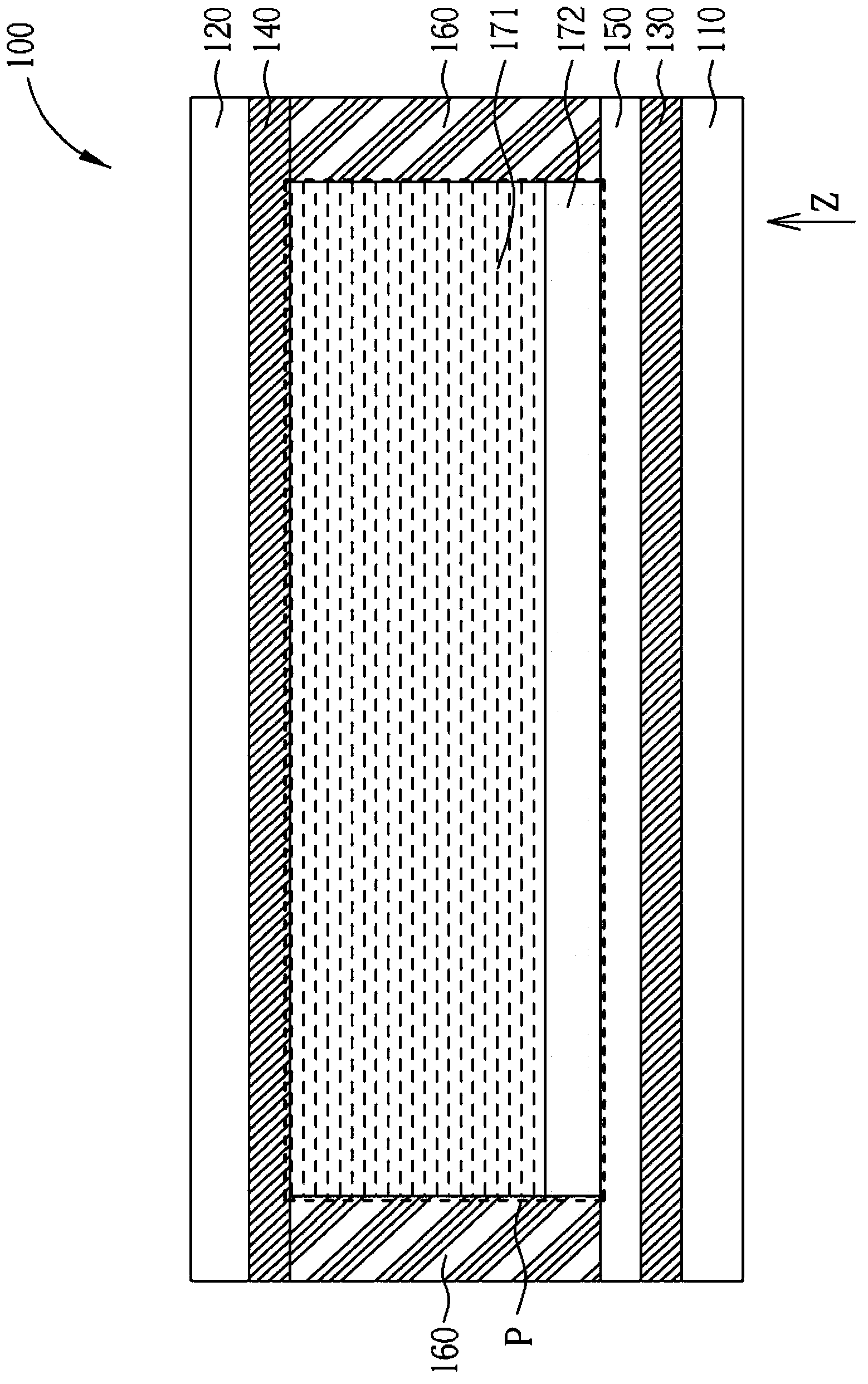
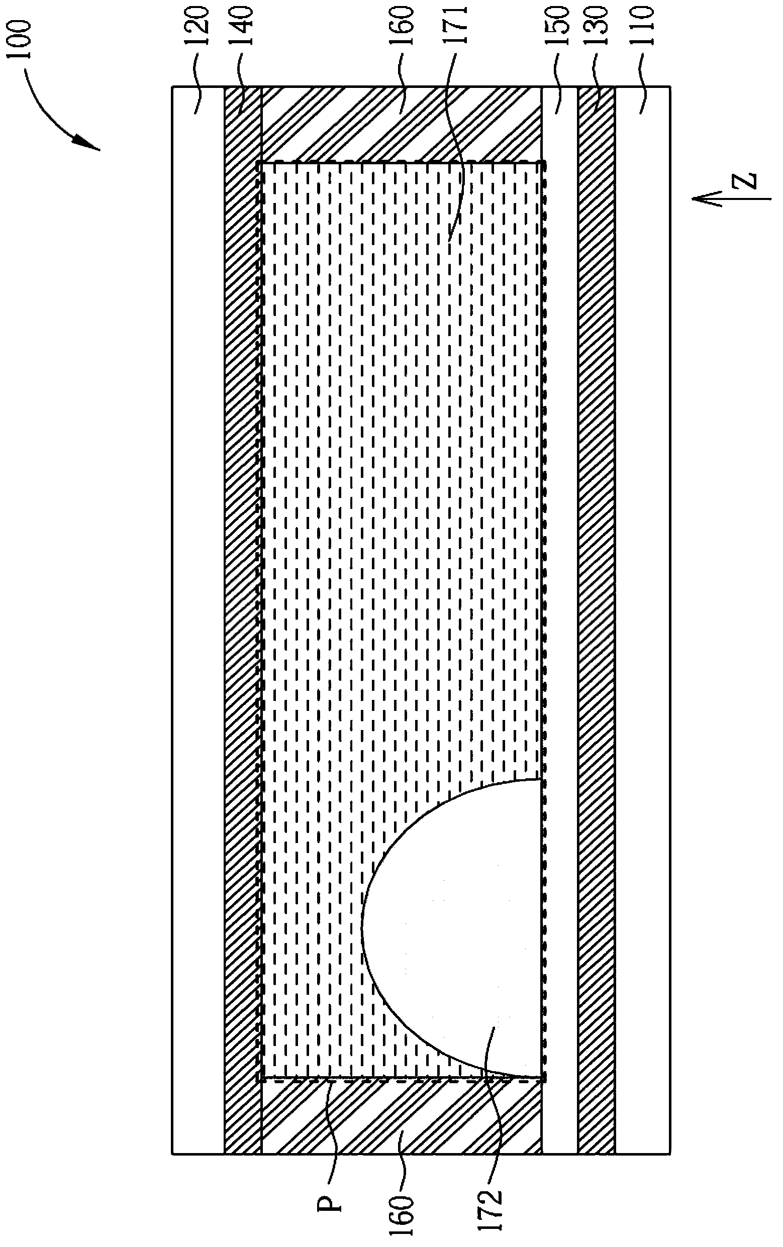
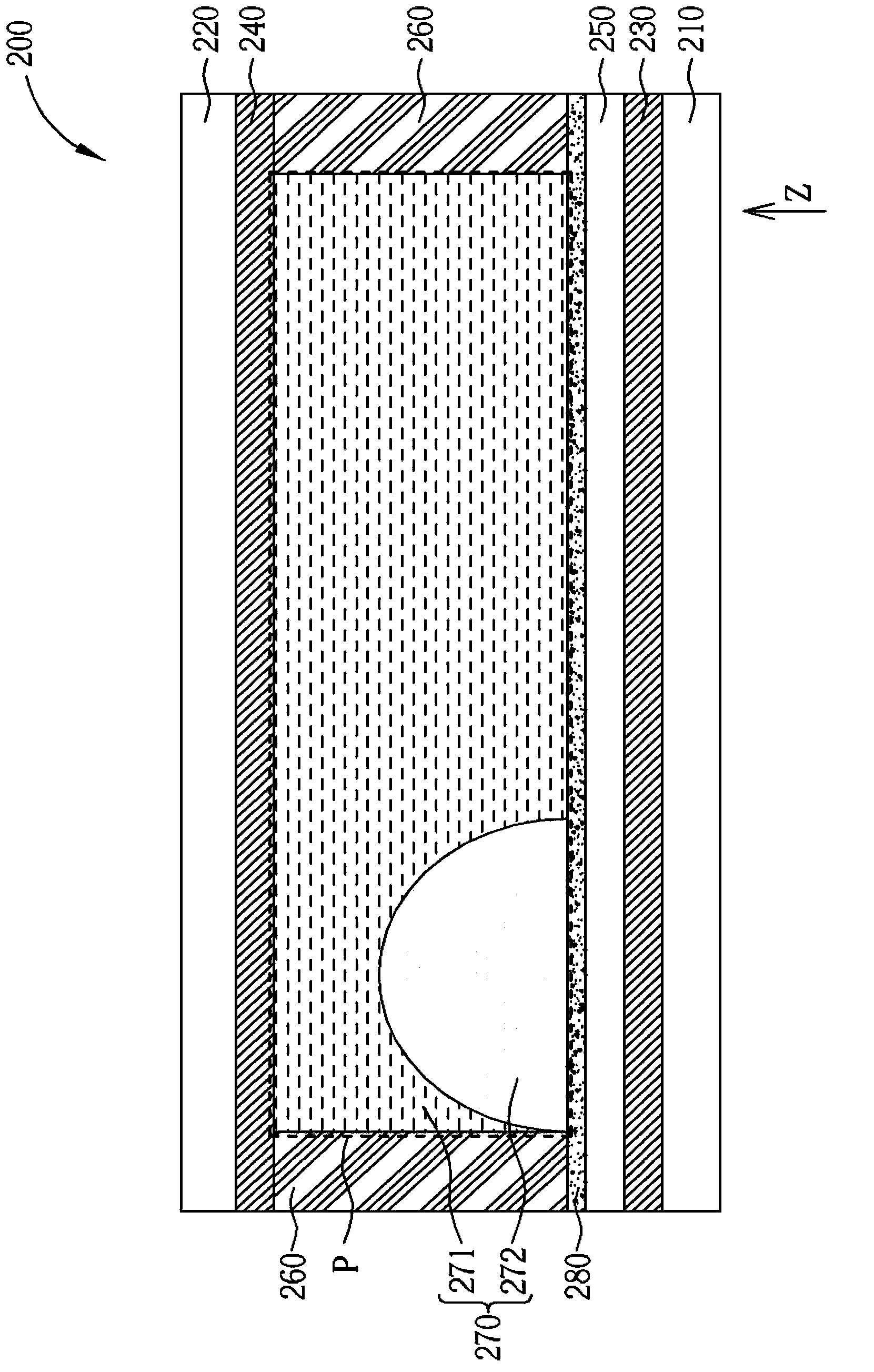
[0026] Please refer to Figure 3 to Figure 6 . image 3 and Figure 4 Shown is a schematic diagram of an electrowetting display device according to a preferred embodiment of the present invention. Figure 5 and Image 6 Shown is a schematic diagram of the driving status of the electrowetting display device of this embodiment. in Figure 5 is corresponding image 3 ,and Image 6 is corresponding Figure 4 . For the convenience of description, the drawings of this embodiment are only schematic diagrams for easy understanding of the present invention, and the detailed proportions thereof can be adjusted according to design requirements. Such as...


PUM


Abstract

The invention discloses an electrowetting display device. The electrowetting display device includes a lower substrate, an upper substrate, a medium layer, a lower electrode, an upper electrode, and a molecular chain layer. The medium layer is disposed between the lower substrate and the upper substrate. The medium layer includes a first medium and a second medium separated from each other. The first medium is a light transmission medium, and the second medium is a light-shielding medium. The lower electrode is disposed between the medium layer and the lower substrate. The molecular chain layer is disposed between the medium layer and the lower electrode. The molecular chain layer includes molecular chains. Each molecular chain has a first section and a second section. The first section is used to attract the first medium or repel the second medium. The second section is used to attract the second medium or repel the first medium.

Description

technical field [0001] The present invention relates to an electrowetting display device, in particular to an electrowetting display device which uses changes in the arrangement of molecular chains to generate water-repelling and lipophilic or oil-repelling and hydrophilic effects. Background technique [0002] figure 1 and figure 2 Shown is a schematic diagram of a conventional electrowetting display device. Such as figure 1 and figure 2 As shown, the conventional electrowetting display device 100 includes a lower substrate 110 and an upper substrate 120 disposed opposite to each other. A lower electrode 130 , an upper electrode 140 , an insulating layer 150 , a sealant 160 , a polar aqueous solution 171 and an ink 172 are disposed between the lower substrate 110 and the upper substrate 120 . The display area P is defined by the lower substrate 110 , the upper substrate 120 and the sealant 160 . When no voltage is applied to the lower electrode 130 and the upper ele...

Claims


Application Information

Patent Timeline
Patent Type & Authority Applications(China)
IPC IPC(8): G02B26/02G09G3/34
CPCG09G3/348G02B26/005
Inventor 王志源陈承义周承毅赖台晏吴育骅李宸维
Owner WINTEK CORP
Features
  • R&D
  • Intellectual Property
  • Life Sciences
  • Materials
  • Tech Scout
  • Unparalleled Data Quality
  • Higher Quality Content
  • 60% Fewer Hallucinations
Learn More