
Current mode voltage regulator with auto-compensation

A voltage regulator, automatic compensation technology, applied in the direction of adjusting electrical variables, control/regulating systems, instruments, etc., can solve problems such as overshoot and unstable output voltage

Active Publication Date: 2014-01-15
ANALOG DEVICES INT UNLTD
View PDF4 Cites 12 Cited by
  • Summary
  • Abstract
  • Description
  • Claims
  • Application Information

AI Technical Summary

Problems solved by technology

The described technique must avoid instability and output voltage overshoot during the automatic compensation process

Method used


Image

  • Current mode voltage regulator with auto-compensation
  • Current mode voltage regulator with auto-compensation
  • Current mode voltage regulator with auto-compensation

Examples


Embodiment Construction

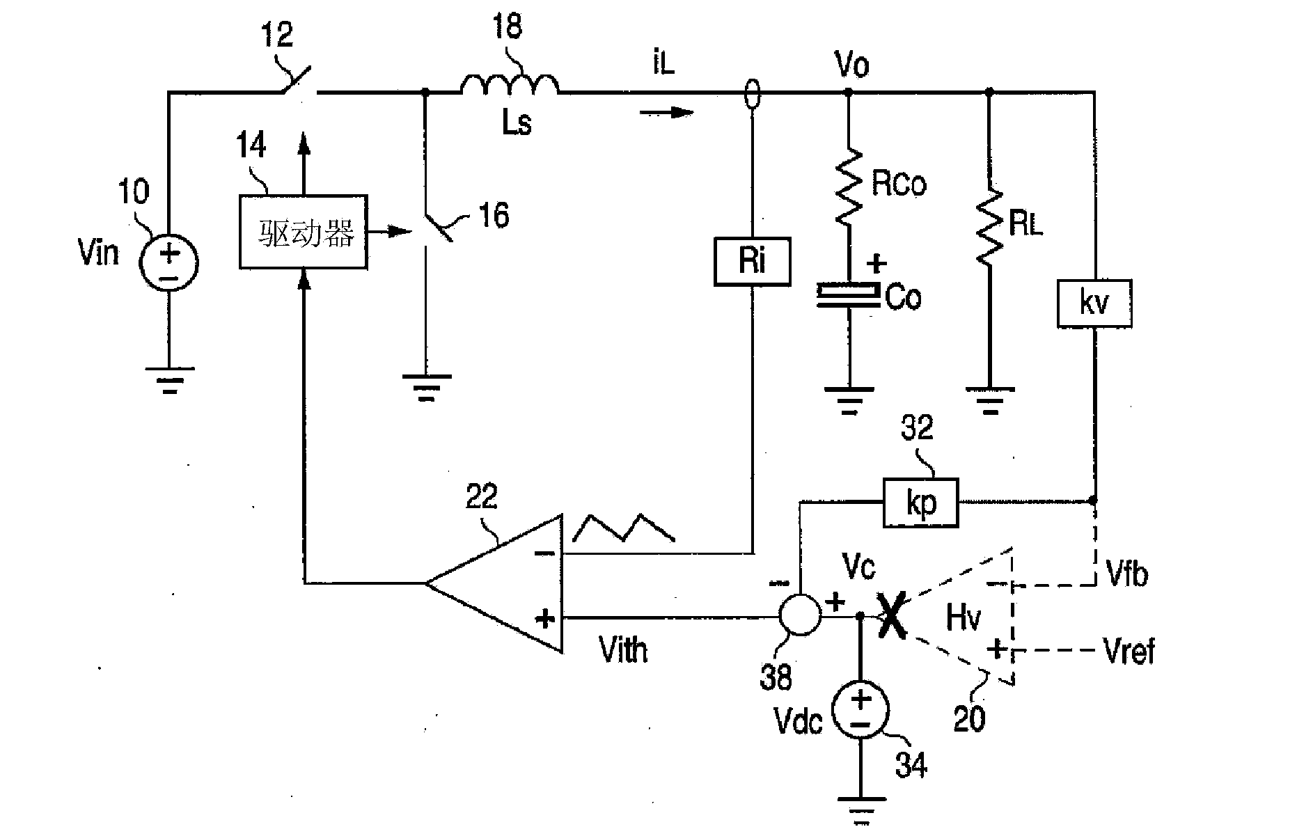
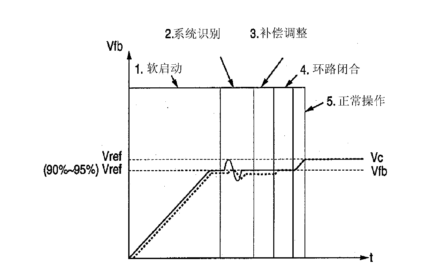
[0035] The various figures illustrate stages of the automatic compensation process by highlighting only the hardware used during that stage, but the actual regulator hardware is unchanged during the process. will combine Figure 15 The flow chart describes the figure.

[0036] An example of a conventional current-mode buck regulator is used in the figure; however, the automatic compensation technique can be applied to all types of current-mode regulators.

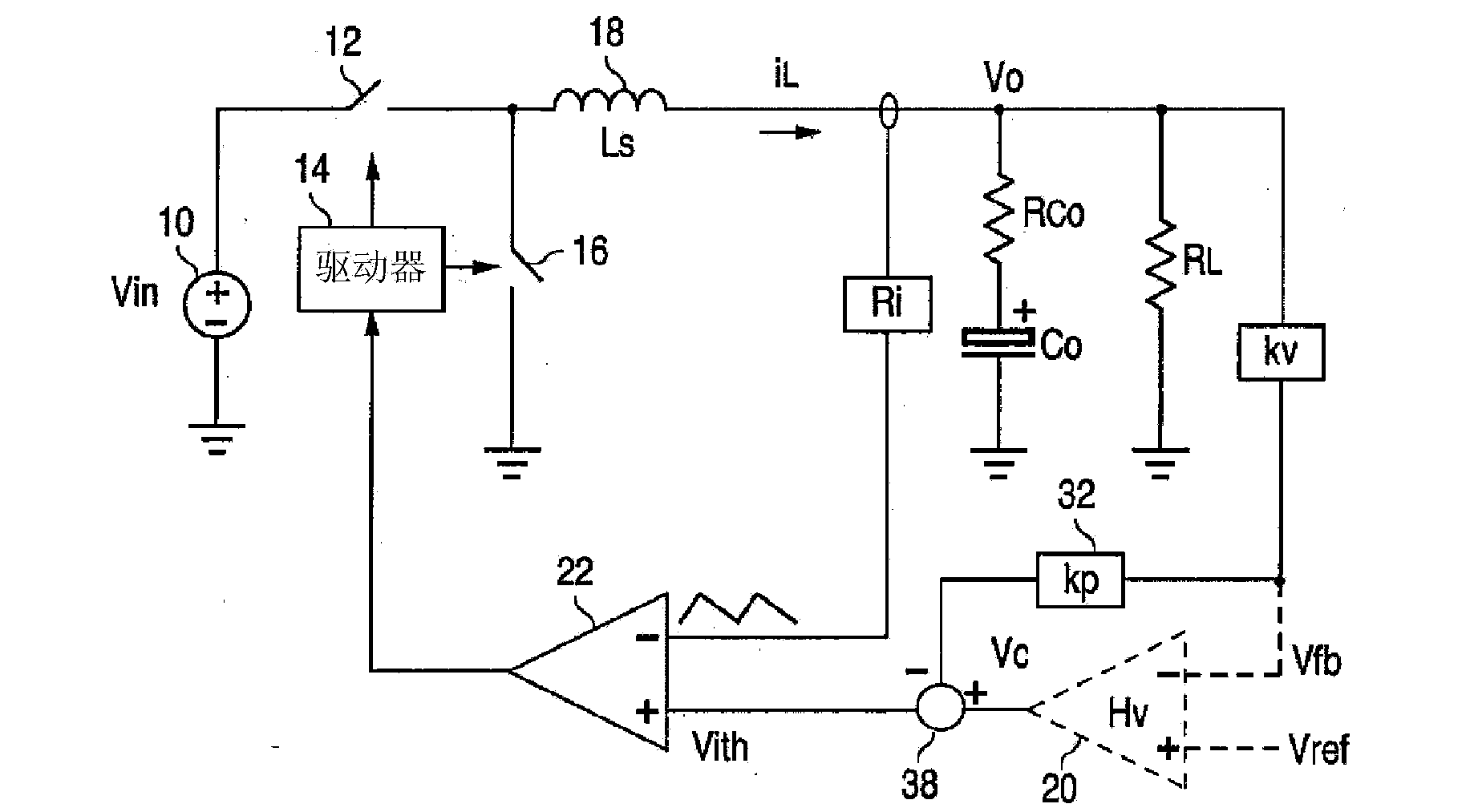
[0037] figure 1 General aspects of a certain current mode regulator modified in accordance with one embodiment of the invention are described. Since current mode regulators are well known, only a brief explanation of their normal operation is provided herein for completeness.

[0038] An unregulated input voltage source 10 is applied to a power switch 12, which may be a transistor. The driver 14 controls the duty cycle of the power switch 12 and the synchronous rectifier switch 16 (which may be transistors). In another e...


PUM


Abstract

The invention relates to a current mode voltage regulator with auto-compensation. In a method for automatically compensating a voltage regulator, an error amplifier (20) and compensation network are initially disconnected from a feedback loop, a DC bias voltage (34) is applied to the feedback loop to cause the regulator's output voltage to be at 90% of its nominal value and an AC perturbation signal is then added to the DC bias voltage to cause the output voltage to have a ripple at a frequency of the AC signal. The gain of the feedback loop and the phase difference between the AC signal and the ripple is then measured. The measured values are then used to automatically adjust operating characteristics of the error amplifier and the compensation network such that, when these components are connected back in the feedback loop during normal operation, the feedback loop has the desired gain and phase margin at the frequency of the AC signal, such as the loop's unity gain frequency.

Description

technical field [0001] The present invention relates to voltage regulators and, in particular, to a current mode voltage regulator with automatic compensation for improving the stability of the feedback loop. Background technique [0002] Current-mode voltage regulators regulate the output voltage by regulating the current through the inductor. The regulator uses both a relatively fast current feedback loop (which senses current) and a slower voltage feedback loop (which senses voltage) to control the output voltage. Stability is a concern due to phase shift and delay in the feedback loop. Oscillation can be avoided by choosing a compensation component (eg, a capacitor-resistor network) connected to the voltage feedback loop that attenuates the loop gain above a certain frequency and provides the desired phase shift. The optimal component values ​​are determined based on the final design of the regulator, and typically require the user to calculate or manually test and det...

Claims


Application Information

Patent Timeline
IPC IPC(8): G05F1/46
CPCH02M3/156
Inventor 黎坚金东·亨利·张
Owner ANALOG DEVICES INT UNLTD
Features
  • Generate Ideas
  • Intellectual Property
  • Life Sciences
  • Materials
  • Tech Scout
  • Unparalleled Data Quality
  • Higher Quality Content
  • 60% Fewer Hallucinations
Learn More