Method for adjusting output power of synchronous generator
A technology of synchronous generator and output power, which is applied in the direction of controlling the generator through the change of the magnetic field
Inactive Publication Date: 2014-01-15
丁士来
View PDF0 Cites 11 Cited by
- Summary
- Abstract
- Description
- Claims
- Application Information
AI Technical Summary
Problems solved by technology
The permanent magnet synchronous generator has the advantages of small size, light weight, high efficiency, and simple structure, but it has not been widely used in the field of power generation due to the problem of voltage regulation.
Method used
View moreImage
Smart ImageViewing Examples
Examples
Embodiment Construction
Login to View More PUM
 Abstract
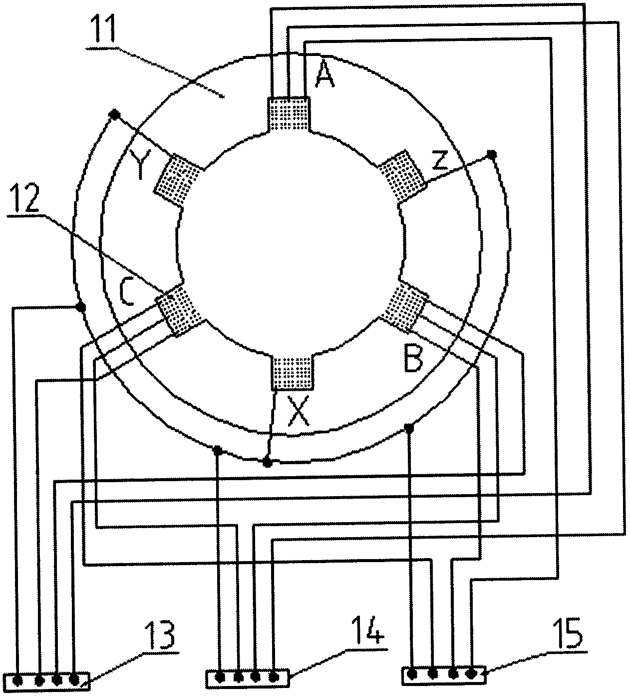
The invention relates to a method for adjusting output power of a synchronous generator. The method is implemented by the utilization of properties as follows: magnitude of excitation magnetic field during operation of the synchronous generator is unrelated to input power of the generator; magnitude of input power is proportional to magnitude of a load connected to an induction coil, current intensity and number of turns of the induction coil; and when rotor speed of the synchronous generator is unchanged, magnitude of excitation magnetic field is proportional to magnitude of output voltage and is proportional to number of turns of an armature coil. During design, excitation flux of a rotor is designed to be higher, and the maximum value is unchanged during operation of the generator. Then, a stator coil is designed to be a structural form capable of adjusting the number of turns. During operation of the generator, it is ensured that output voltage and frequency of the generator are rated values by adjusting or selecting the number of turns of the corresponding stator coil and the magnitude of input power according to the condition of the load. In addition, the method used in a permanent magnet synchronous generator has a more obvious energy-saving effect.
Description
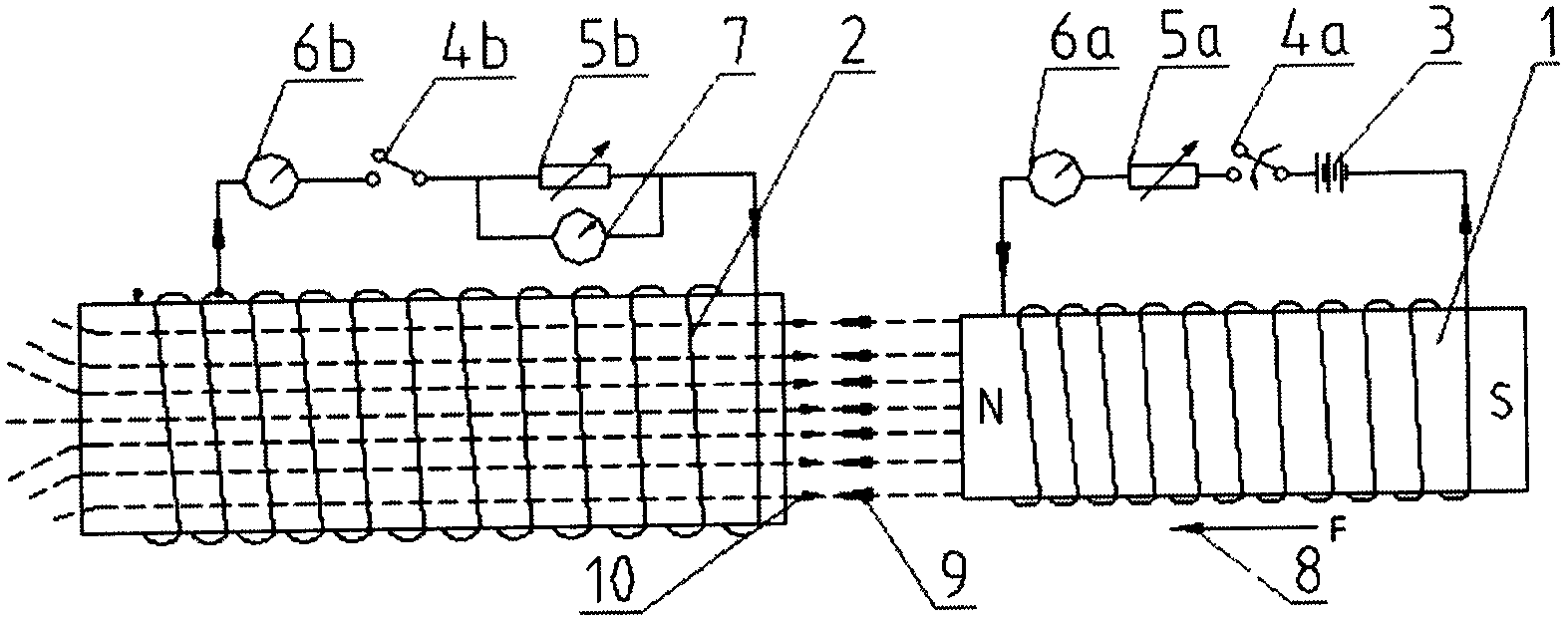
Technical field [0001] The invention relates to a method for adjusting the output power of a synchronous generator, and belongs to the field of AC power generation. Background technique [0002] In electromagnetics, the law of electromagnetic induction is summarized through a large number of experiments. figure 1 A schematic diagram showing an example of electromagnetic conversion. In the figure, when the N pole of the electromagnet 1 that is connected to the direct current moves toward the induction coil 2, the magnetic flux passing through the area enclosed by the induction coil 2 gradually increases. According to the law of electromagnetic induction, between the two ends of the induction coil 2 Induced electromotive force, when the electromagnet 1 moves at a constant speed, the voltage across the induction coil 2 is related to the magnetic field strength of the electromagnet 1 and the number of turns of the induction coil 2. The stronger the magnetic field strength of the ele...
Claims
Login to View More Application Information
Patent Timeline
 IPC IPC(8): H02P9/14
Inventor 丁士来丁颖颖李晓利郭国勤丁世东顾康李振中
Owner 丁士来
Features
- R&D
- Intellectual Property
- Life Sciences
- Materials
- Tech Scout
- Unparalleled Data Quality
- Higher Quality Content
- 60% Fewer Hallucinations
Learn More Browse by: Latest US Patents, China's latest patents, Technical Efficacy Thesaurus, Application Domain, Technology Topic, Popular Technical Reports.
© 2025 PatSnap. All rights reserved.Legal|Privacy policy|Modern Slavery Act Transparency Statement|Sitemap|About US| Contact US: help@patsnap.com


