
Cyclone separation dust cup of dust collector

A technology of cyclone separation and cyclone separator, applied in the direction of suction filter, etc., can solve the problems of use impact, clogging of secondary dust separator, poor separation effect, etc., and achieve the effect of increasing pressure and improving separation efficiency.

Active Publication Date: 2014-01-22
胡海荣
View PDF7 Cites 6 Cited by
  • Summary
  • Abstract
  • Description
  • Claims
  • Application Information

AI Technical Summary

Problems solved by technology

[0003] For example, the Chinese patent No. 201110400853.0 discloses a cyclone-separated dust cup for a vacuum cleaner, which includes a cup with a tangential first-stage air inlet on the side wall, a dust cup cover with an air outlet that matches the cup, and The cyclone separation body arranged in the cup is characterized in that the cyclone separation body includes a main body, a plurality of second-stage air inlets are provided in the middle of the side wall of the main body, and the middle and lower parts of the main body are connected to There is a cyclone separator dust cover, below the cyclone separator dust cover, between the lower wall of the cyclone separator and the cup is the first-stage dust collection chamber, which constitutes the first-stage separator; the upper part of the inner side of the main body There are a plurality of cyclone separation cores distributed in the cyclone separation core seat, the cyclone separation core is provided with an air guide with an air inlet channel, and the airflow from the cyclone separation core is introduced into the lower separator. The middle part of the side wall of the separation core is provided with a third-stage air inlet, and the edge of the middle and lower parts of the cyclone separation core is connected with a cyclone separation core dust cover, below the cyclone separation core dust cover, between the inside of the main body and the lower separator The space between is the second-level dust collection chamber, which constitutes the second-level separator; the center of the cyclone separator is provided with a central cyclone separator, as a third-level separator; the cyclone separator and the central cyclone separator Fixed with the bottom of the cup body; the main defect of this type of cyclone separation dust cup is that the first-stage cyclone directly rotates in the dust cup body, and since the deposited dust and the rotating cyclone are on the same rotating surface, the deposited dust is in use It will also not be taken away by the cyclone at the back, and enter the secondary separator from the small hole. The separation effect of the primary separator is relatively poor, which greatly increases the pressure of the secondary separator; the dust outlet of the secondary cyclone separator is directly Facing the small particle dust accumulation chamber in the center, it is also easy to cause the airflow of dust to be carried again, resulting in a decrease in separation efficiency;
[0005] Since the first-level dust separator and the second-level dust separator are in the same cavity, it is inevitable that a small amount of unseparated air will directly enter the air inlet of the second-level dust separator from the first-level dust separator with the airflow, resulting in the second-level separation. The workload increases, and if the filter is directly placed above the dust collection chamber, it is easy to cause the raised dust to enter from the mesh of the filter, thereby blocking the secondary dust separator, and the separation effect is poor, which affects the use

Method used


Image

  • Cyclone separation dust cup of dust collector
  • Cyclone separation dust cup of dust collector

Examples


Embodiment Construction

[0024] The present invention will be further described in detail below in conjunction with the accompanying drawings and embodiments.

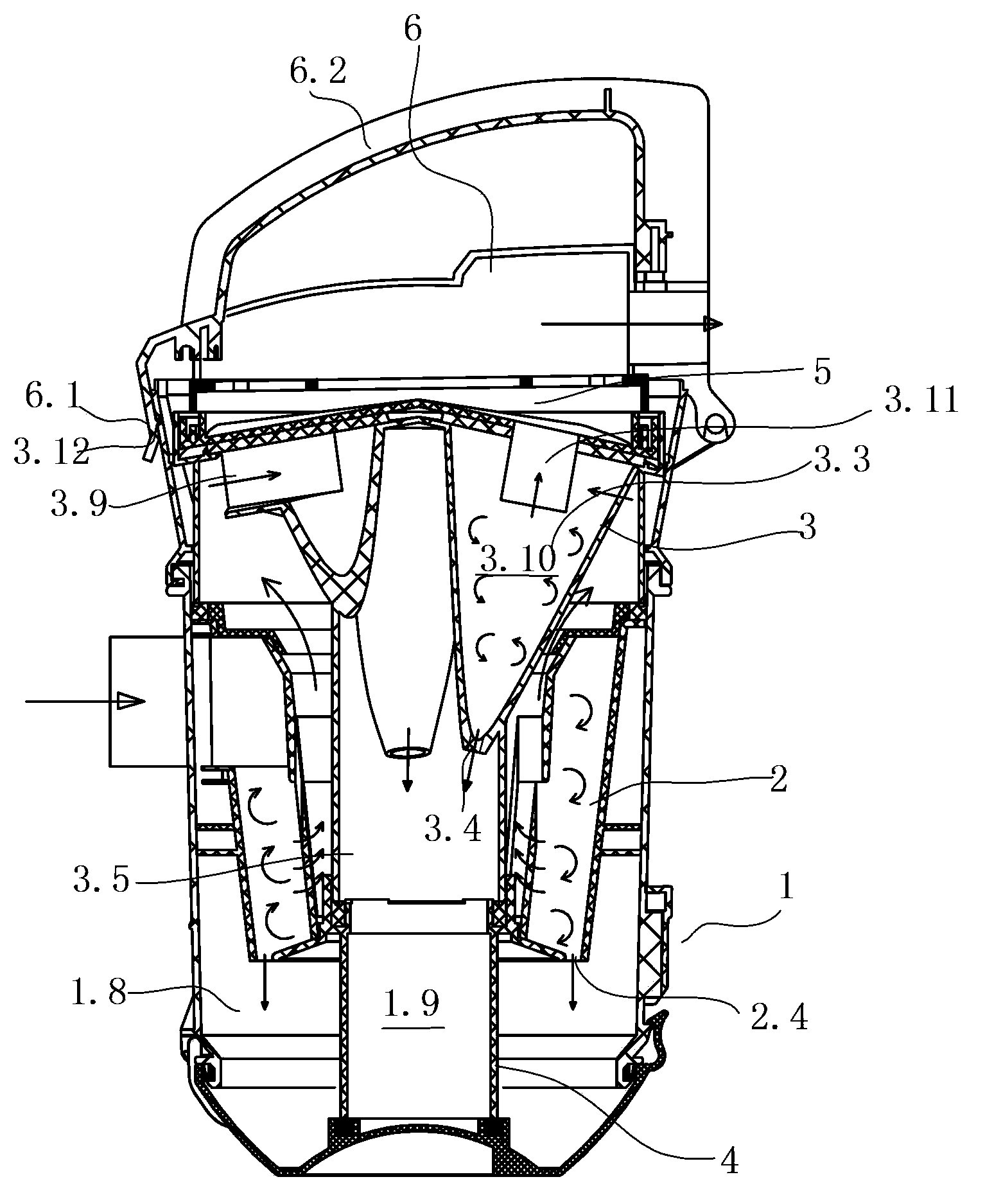
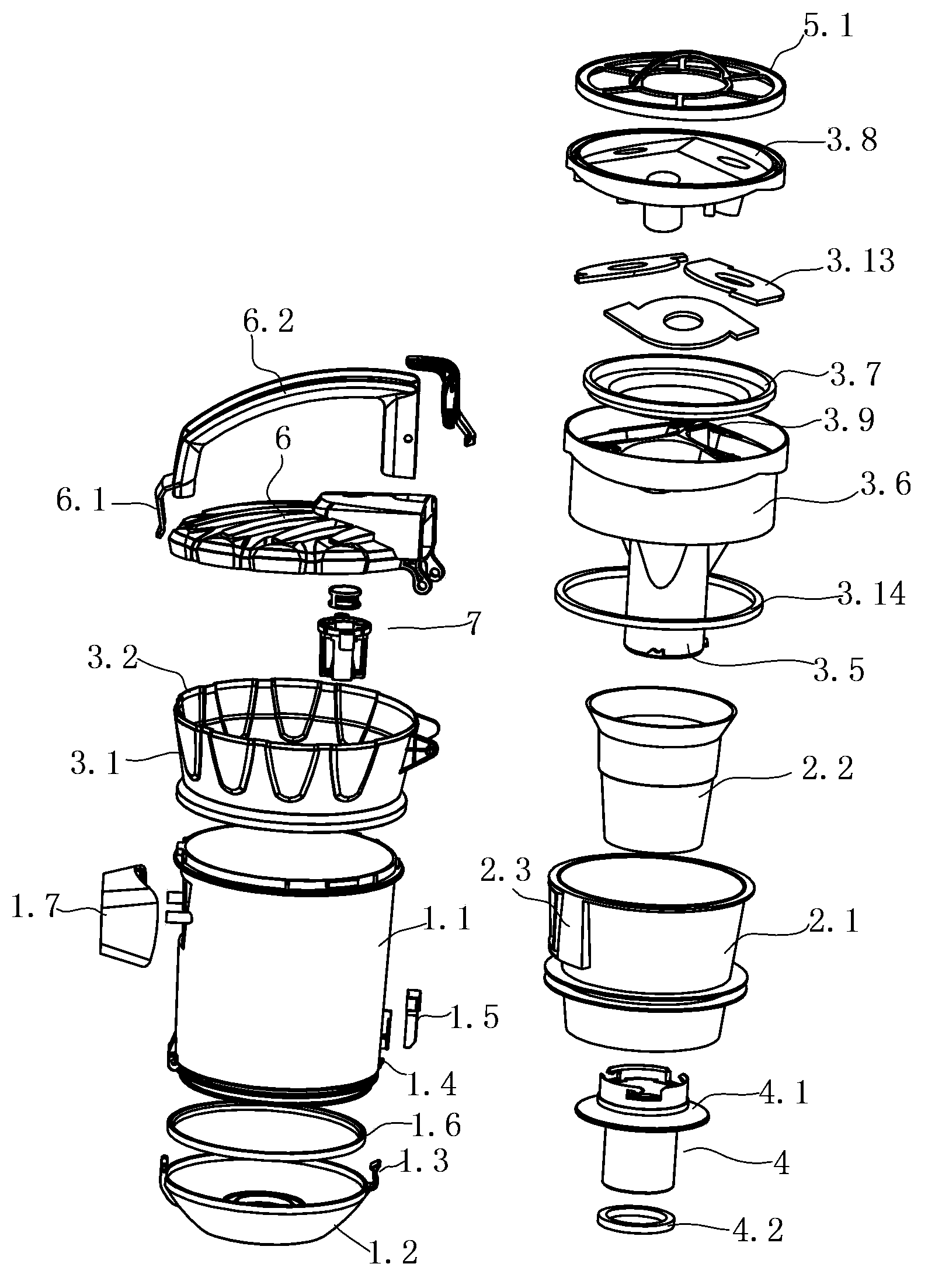
[0025] As shown in the figure, a dust cup for vacuum cleaner cyclone separation includes main components such as a cup body 1, a dust cup cover, a primary filter 2, and a secondary cyclone separator 3, wherein the cup body 1 includes a cup body 1.1 and a cup body 1.1. The cup base 1.2, one side of the cup body 1.1 and the cup base 1.2 are connected by a pivot, and the other side of the cup body 1.1 and the cup base 1.2 is provided with a connecting buckle, so that the buckle body 1.3 of the cup base can be fastened to the cup On the flange 1.4 protruding from the bottom of the main body, above the flange, the outer surface of the cup main body is provided with a button switch 1.5 and a button body 1.3 for cooperation, and the bonding surface of the cup base 1.2 and the cup main body 1.1 is provided with an annular sealing groove and inner linin...


PUM


Abstract

The invention discloses a cyclone separation dust cup of a dust collector. The cyclone separation dust cup of the dust collector is characterized in that a first-level filter structure is that an outer sleeve and an inner sleeve of a first-level filter are arranged on the portion, below a general air inlet, in a cup body, the radial radius of the first-level filter is downwards and gradually reduced, the whole side wall of the first-level filter is of a sleeve shape, an air inlet is formed in the outer sleeve and communicated with the general air inlet of the cup body, and a dust falling opening exists between the outer sleeve and the inner sleeve and is communicated with a large-particle-dust collection cavity arranged on the outer layer of the bottom of the cup body; a second-level cyclone separator structure is that a cyclone body sleeve is arranged above the first-level filter, second-level cyclone separator units are installed in the cyclone body sleeve, the second-level cyclone separator units are distributed in the circumferential direction, the central axis of each second-level cyclone separator unit inclines outwards, and a second-level cyclone separator is composed of the second-level cyclone separator units which are connected in parallel, a dust discharging opening is communicated with a small-particle-dust collection cavity through a central pipe, and the small-particle-dust collection cavity is formed in the inner layer of the bottom of the cup body; outlets of the second-level cyclone separator units are communicated through a three-level filter and are communicated with a general air outlet of a dust cup cover. The cyclone separation dust cup of the dust collector is reasonable and practical in overall structure, small in air resistance and high in separation efficiency.

Description

technical field [0001] The invention relates to a cyclone-separated dust cup for a vacuum cleaner, in particular to a cyclone-separated dust cup. Background technique [0002] The dust cup used for filtering is the main part of the vacuum cleaner. In order to better separate impurities such as dust from the air, most existing vacuum cleaners use a cyclone dust cup for secondary separation. The air containing impurities enters the first-stage separator along the tangential direction, and makes a rotary motion from top to bottom. During the rotary process, large particles and heavier impurities collide with the first stage due to their greater density than air and greater centrifugal force. The inner wall of the separator loses its inertia and falls into the dust collecting chamber below to be separated from the air. The finer impurities and air enter the second-stage separator, and the fine dust collides with the inner wall of the second-stage separator and loses inertia and...

Claims


Application Information

Patent Timeline
IPC IPC(8): A47L9/16
Inventor 胡海荣
Owner 胡海荣
Features
  • Generate Ideas
  • Intellectual Property
  • Life Sciences
  • Materials
  • Tech Scout
  • Unparalleled Data Quality
  • Higher Quality Content
  • 60% Fewer Hallucinations
Learn More