Check patentability & draft patents in minutes with Patsnap Eureka AI!

Roller coaster stand column structure and installation method

A roller coaster and column technology, which is applied in the field of roller coaster column structure and installation, can solve the problems that cannot meet the positioning accuracy of track column bolt connection, poor positioning accuracy of track column connection points, and cannot meet the safety of train operation, etc., to achieve no gap contact , high positioning accuracy, and the effect of improving the force condition of the column foot

Inactive Publication Date: 2014-01-22
北京中冶设备研究设计总院有限公司 +1
View PDF5 Cites 4 Cited by
  • Summary
  • Abstract
  • Description
  • Claims
  • Application Information

AI Technical Summary

Problems solved by technology

This method has obvious disadvantages: the column is in place at one time, the positioning accuracy of the connection point of the track column is poor, and it cannot be adjusted; at the same time, the column foot plate is welded on site, and its welding deformation causes the column foot plate and the foundation to be not tightly bonded. When the train is running, the column foot Under alternating stress, prone to cracks and other defects
Therefore, the traditional roller coaster column installation method cannot meet the positioning accuracy of the track column bolt connection, nor can it meet the requirements of train operation safety

Method used


Image

  • Roller coaster stand column structure and installation method
  • Roller coaster stand column structure and installation method

Examples


Embodiment Construction

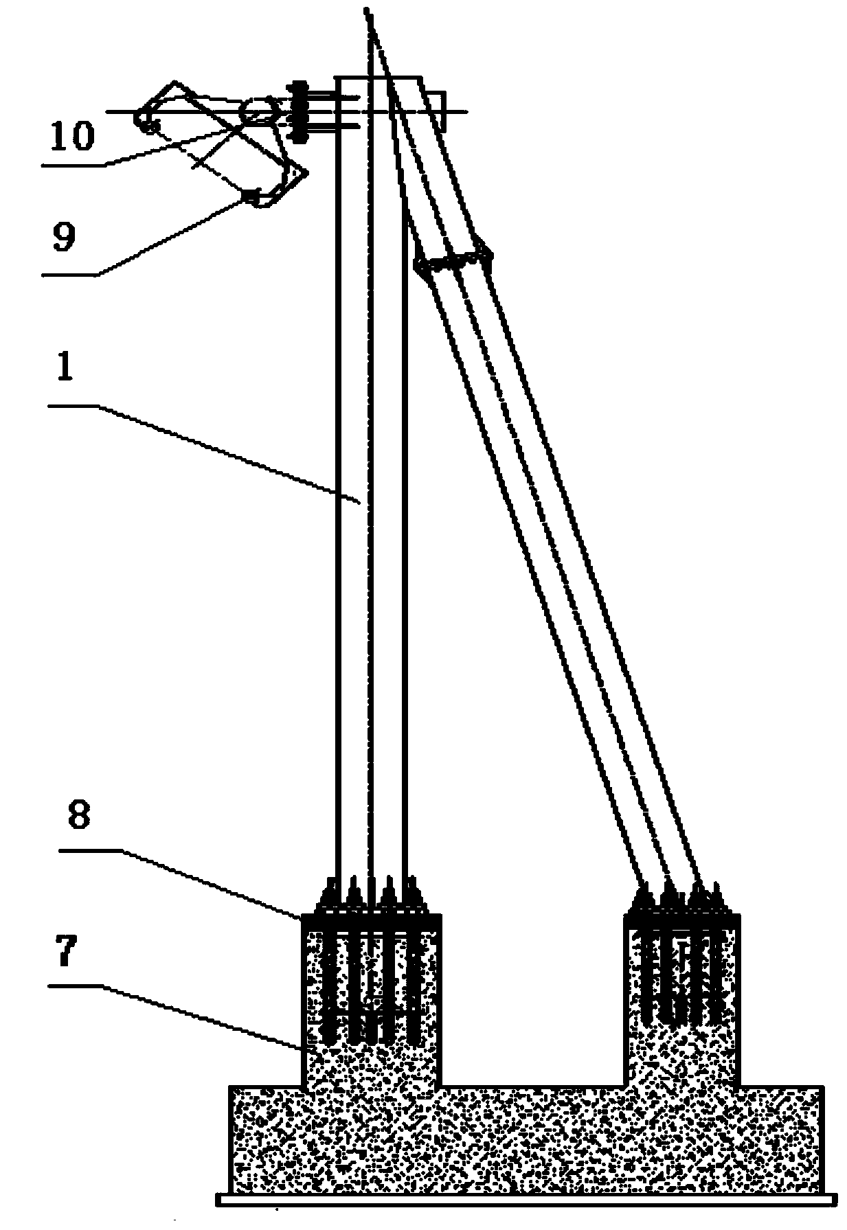
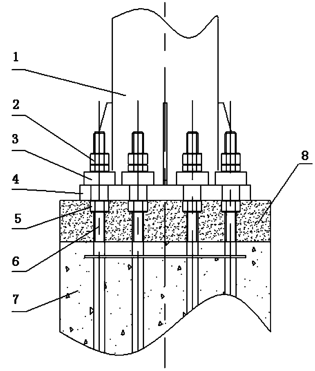
[0009] A roller coaster column structure and installation method according to the embodiment of the present invention will be further described in detail below in conjunction with the accompanying drawings: figure 1 And attached figure 2 A roller coaster column structure is disclosed in figure 1 For the column installation diagram, figure 2 It is the installation structure diagram of the column foot; the column structure of the roller coaster mainly includes the column 1, the anchor nut 2, the spacer 3, the column foot plate 4, the adjusting nut 5, the anchor bolt 6, the foundation 7, the secondary grouting layer 8, the track 9, the connection Point 10; each anchor bolt 6 is fitted with an adjusting nut 5 and spacer 3; the spacer 3 is located in the middle of the anchor nut 2 and the column foot plate 4; the secondary grouting layer 8 is located above the foundation 7 and on the column foot plate 4; the adjusting nut 5 sleeved on the anchor bolt 6 is located in the seconda...


PUM


Abstract

The invention provides a roller coaster stand column structure. The roller coaster stand column structure comprises a stand column, anchor nuts, cushion blocks, heel slabs, adjusting screw nuts, foundation bolts, a foundation, a secondary grouting layer, a rail and a connecting point, wherein each foundation bolt is sleeved with one of the adjusting screw nuts and one of the cushion blocks, each cushion block is located between one of the anchor nuts and one of the heel slabs, the diameter of a foundation bolt hole in each heel slab is larger than the diameter of the foundation bolt, and the heel slabs and the stand column are welded into a whole. The invention further provides an installation method of the roller coaster stand column structure. The installation method is characterized in that the adjusting screw nuts are firstly arranged on the foundation bolts respectively, the stand column is then erected, fine adjustment is conducted in the X direction, the Y direction and the Z direction, the anchor nuts are initially screwed so that the stand column can be fixed after the positioning precision of the connecting point of the stand column and the rail is met, secondary grouting and maintenance of the foundation are conducted after overall installation of the stand column is completed, the foundation bolts are then fastened, and installation is completed. The roller coaster stand column structure and the installation method have the advantages that the field welding of the heel slabs is avoided, the positioning precision of the rail and the stand column is high, and train operation is safe and reliable.

Description

Technical field: [0001] The invention relates to a roller coaster structure in the amusement industry, in particular to a roller coaster column structure and an installation method. Background technique: [0002] In the prior art, roller coaster track column installation is one of the core technologies for roller coaster installation, and its precision and quality directly affect the quality and even safety of roller coaster train operation. In order to meet passengers' higher and higher requirements for the smoothness and smoothness of roller coaster operation, the roller coaster track and columns are connected by bolts. A roller coaster has dozens or even hundreds of connection points, and each connection point has different three-dimensional space coordinates. And the coordinate points are very different, so higher requirements are put forward for the installation accuracy and quality of the track column. At present, the method adopted for the installation of the roller ...

Claims


Application Information

Patent Timeline
IPC IPC(8): A63G21/04
Inventor 刘兴科李继成刘忠胜
Owner 北京中冶设备研究设计总院有限公司
Features
  • R&D
  • Intellectual Property
  • Life Sciences
  • Materials
  • Tech Scout
  • Unparalleled Data Quality
  • Higher Quality Content
  • 60% Fewer Hallucinations
Learn More