Method for target material component welding

A welding method and target technology, which are applied in welding equipment, non-electric welding equipment, metal processing equipment, etc., can solve the problems of poor welding bonding rate of target components, inability to achieve large-area welding, and low welding efficiency, and improve welding efficiency. Bonding rate and welding strength, satisfying long-term stable production and use of target materials, and high welding efficiency

Inactive Publication Date: 2014-01-22
KONFOONG MATERIALS INTERNATIONAL CO LTD
View PDF7 Cites 27 Cited by
  • Summary
  • Abstract
  • Description
  • Claims
  • Application Information

AI Technical Summary

Problems solved by technology

[0006] The technical problem to be solved by the present invention is that the welding efficiency is low when the tungsten target and the back plate are welded together by the existing welding method, and the formed target assembly has poor welding bonding rate, low welding strength, large deformation, and the current Some welding methods cannot achieve large-area welding, so they cannot meet the needs of long-term stable production and use of targets

Method used


Image

  • Method for target material component welding
  • Method for target material component welding
  • Method for target material component welding

Examples


Embodiment 1

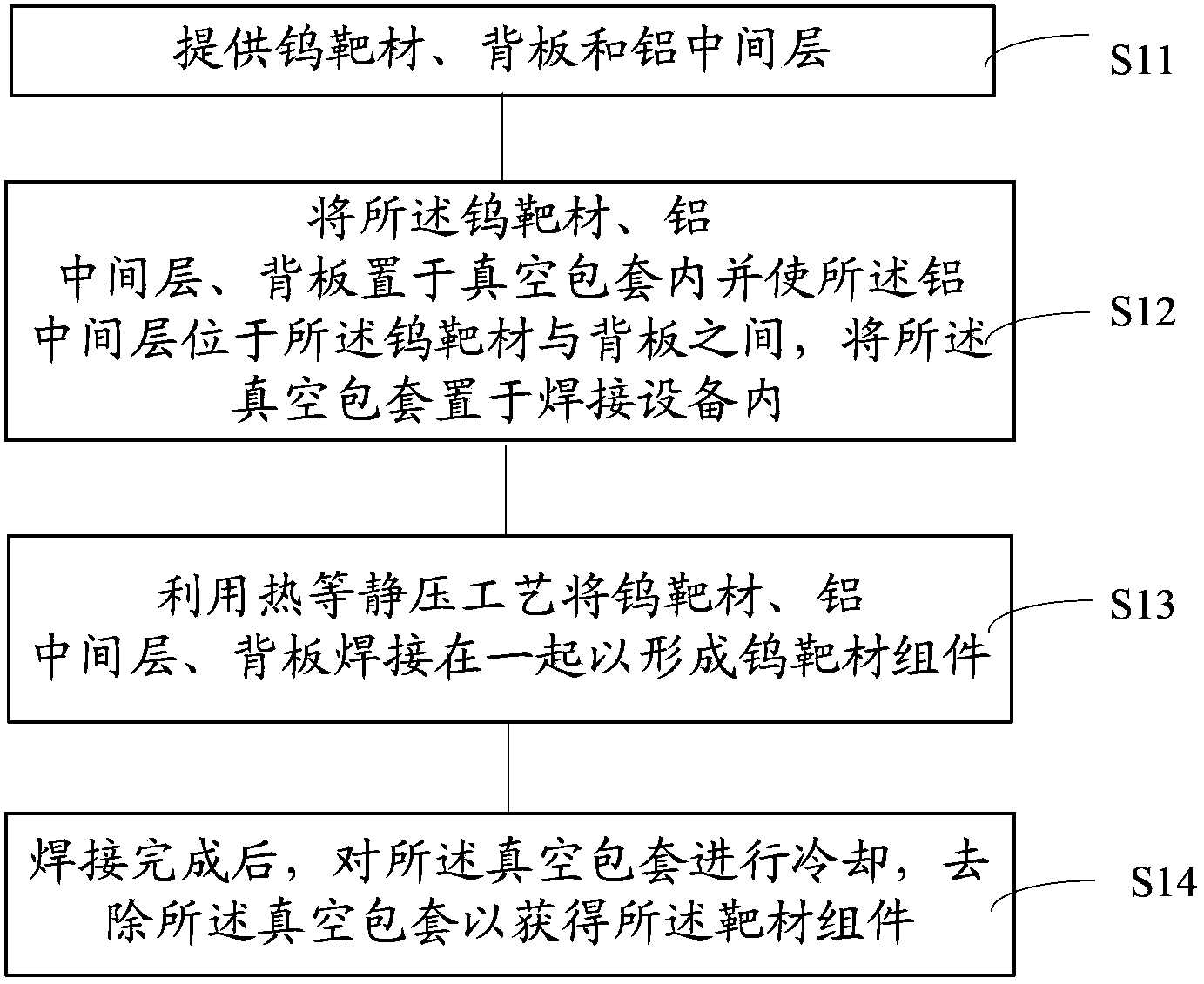
[0058] figure 1 It is the welding method flow chart of target assembly welding method embodiment 1 of the present invention. Include the following steps:

[0059] Execute step S11 to provide a tungsten target, a back plate and an aluminum intermediate layer;

[0060] Execute step S12, place the tungsten target material, the aluminum intermediate layer, and the back plate in the vacuum envelope and make the aluminum intermediate layer between the tungsten target material and the back plate, and place the vacuum envelope In welding equipment;

[0061] Execute step S13, using a hot isostatic pressing process to weld the tungsten target, the aluminum intermediate layer, and the back plate together to form a target assembly;

[0062] Step S14 is executed, after the welding is completed, the vacuum envelope is cooled, and the vacuum envelope is removed to obtain the target assembly.

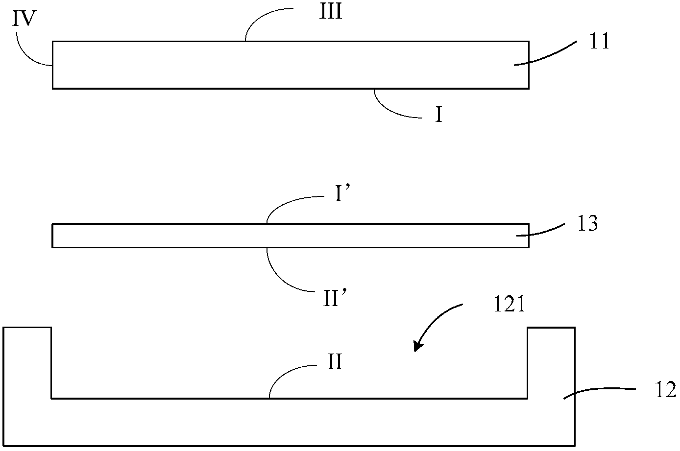
[0063] Please refer to figure 2 , firstly, step S11 is performed to provide a tungsten target...

Embodiment 2

[0101] Figure 11 It is a flow chart of the welding method of the target assembly in the second embodiment of the welding method of the target assembly of the present invention, which shows that when the intermediate layer between the tungsten target and the back plate is formed on the surface of the tungsten target to be welded, the Welding processes for target components such as Figure 11 As shown, it specifically includes the following steps:

[0102] Step S21 is executed to provide a tungsten target and a back plate.

[0103] Step S22 is executed to form an aluminum intermediate layer on the surface of the tungsten target to be welded so that the aluminum intermediate layer and the tungsten target form an integral body.

[0104] Execute step S23, place the tungsten target material and the back plate formed with the aluminum intermediate layer in the vacuum envelope and make the aluminum intermediate layer between the tungsten target material and the back plate, and plac...


PUM

PropertyMeasurementUnit
thicknessaaaaaaaaaa
melting pointaaaaaaaaaa
heightaaaaaaaaaa

Abstract

The invention provides a method for target material component welding. The method comprises the following steps that a tungsten target material, a back board and an aluminum middle layer are provided; the tungsten target material, the aluminum middle layer and the back board are placed in a vacuum bag, the aluminum middle layer is located between the tungsten target material and the back board, and the vacuum bag is arranged in a welding device; the hot isostatic pressure technology is used for welding the tungsten target material, the aluminum middle layer and the back board together to form a target material component; after welding is completed, the vacuum bag is cooled and removed, so that the target material component is obtained. Due to the fat that the aluminum middle layer is additionally arranged between the tungsten target material and the back board, and the hot isostatic pressure technology is used for welding the tungsten target material and the back board together, welding efficiency is improved, the formed target material component is good in welding binding rate, high in welding strength and small in deformation, large-area welding can be achieved, and therefore the requirements for long-term stable production and using of target materials can be met.

Description

technical field [0001] The invention relates to the field of manufacturing semiconductor sputtering targets, in particular to a welding method for target components. Background technique [0002] In the semiconductor industry, the target assembly is composed of a target that meets the sputtering performance and a back plate that can be combined with the target and has a certain strength. The back plate can play a supporting role when the target assembly is assembled to the sputtering base, and has the effect of conducting heat. [0003] During the sputtering process, the working environment of the target assembly is relatively harsh. The ambient temperature of the target assembly is relatively high, for example, 300°C to 600°C; in addition, one side of the target assembly is cooled by cooling water, while the other side is at 10°C. -9 In the high vacuum environment of Pa, a huge pressure difference is formed on the opposite sides of the target assembly; moreover, the targe...

Claims


Application Information

Patent Timeline
Patent Type & Authority Applications(China)
IPC IPC(8): B23K20/14B23K20/16B23K20/24
CPCB23K20/021B23K20/023B23K20/14B23K20/16B23K20/24
Inventor 姚力军相原俊夫大岩一彦潘杰王学泽宋佳
Owner KONFOONG MATERIALS INTERNATIONAL CO LTD
Why Eureka
Try Eureka