Eureka AIR delivers breakthrough ideas for toughest innovation challenges, trusted by R&D personnel around the world.

Oil and gas well exploiting sewage efficient cavitation processing device and method

A high-efficiency technology for mining sewage, applied in chemical instruments and methods, energy wastewater treatment, water/sewage treatment, etc., can solve the problems of no better treatment method, easy blockage and saturation of activated carbon, and little removal effect, etc., to achieve structural Simple, convenient management, good effect

Inactive Publication Date: 2014-11-19
任步海
View PDF5 Cites 0 Cited by
  • Summary
  • Abstract
  • Description
  • Claims
  • Application Information

AI Technical Summary

Problems solved by technology

Experiments in activated carbon adsorption treatment of oil and gas well sewage show that activated carbon adsorption has a certain effect on the removal of COD and total solids, and the removal rate of COD can reach 56.3. The removal effect is not great, the activated carbon is easy to block and saturated, and the failure is fast
To cooperate with the reactor, it is necessary to design a matching treatment process, which is why there is no better treatment method for the treatment of oil and natural gas extraction wastewater.

Method used


Image

  • Oil and gas well exploiting sewage efficient cavitation processing device and method
  • Oil and gas well exploiting sewage efficient cavitation processing device and method
  • Oil and gas well exploiting sewage efficient cavitation processing device and method

Examples


Embodiment Construction

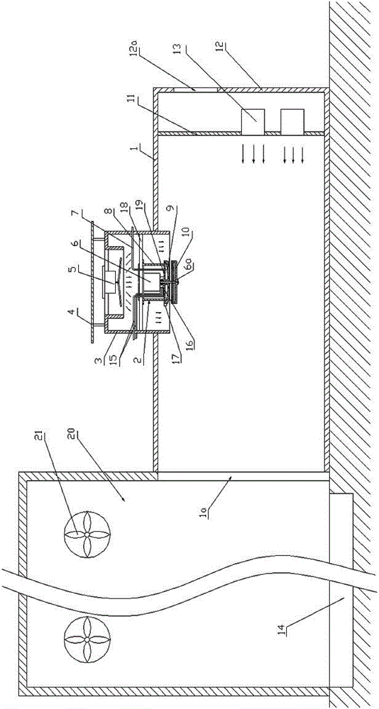
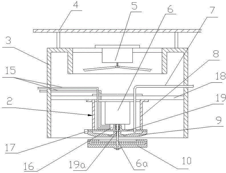
[0053] see Figure 1 to Figure 4 , an embodiment of oil and natural gas drilling and mining sewage treatment equipment, including a cavitation chamber 1, a settling chamber 20, an atomization reaction 2, and a fan. The cavitation chamber 1 and the settling chamber 20 are made of metal plates, and may also be made of concrete poured civil engineering. The depth length of the cavitation chamber 1 is greater than the width, and the depth length of the cavitation chamber 1 is 3-10m, the width is 2-5m, and the height is 2-8m. good. The volume of the settling chamber 20 is larger than that of the cavitation chamber 1, and it is advisable that the inner space of the settling chamber 20 is 2 times or more than the inner space of the cavitation chamber 2. The larger the settling chamber, the better the effect of sedimentation and separation. One end of the cavitation chamber 1 along the depth direction is the first air inlet end, the outer end wall 12 of the first air inlet end is pr...


PUM

PropertyMeasurementUnit
widthaaaaaaaaaa
diameteraaaaaaaaaa
lengthaaaaaaaaaa

Abstract

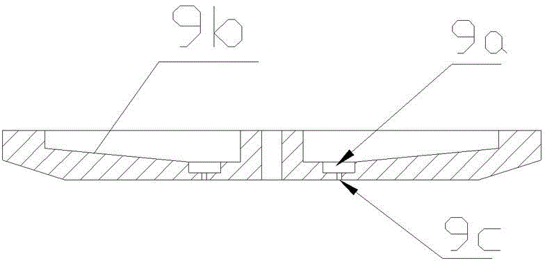
Provided are an oil and gas well exploiting sewage efficient cavitation processing device and method. The device comprises a cavitation chamber, a settling chamber, an atomization reactor and fans. A first fan is arranged at a first air inlet end of the cavitation chamber. The other end of the cavitation chamber is an air outlet and is communicated with the settling chamber. A second air inlet end of the cavitation chamber is provided with a second fan. The atomization reactor is arranged below the second fan and comprises a cylindrical shell body, a motor, a sewage distribution disc and an atomization rotating disc. The motor is placed in the cylindrical shell body. The sewage distribution disc and the atomization rotating disc are arranged below the motor in sequence. The atomization rotating disc is connected with a motor shaft. A plurality of atomization holes are formed in the concave cavity periphery wall of the atomization rotating disc. A sewage conveying pipe extends into the cylindrical shell body and provides water for the sewage distribution disc. Sewage is sprinkled on the high-speed rotating atomization rotating disc from a plurality of water distribution through holes of the sewage distribution disc and is crushed to form atomization air bubbles to be dispersed in the cavitation chamber. The atomization air bubbles collide with each other at high speed under turbulence powerful wind power in different directions, decomposing, expanding, bursting, cavitation evaporating and carried out, and contaminants are separated through extraction.

Description

technical field [0001] The invention relates to the field of sewage treatment, in particular to an oil and natural gas drilling and mining sewage treatment device and treatment method. Background technique [0002] Oil and natural gas are extracted from the depths of the formation. During drilling and oil and gas production, a lot of sewage will be produced. The sewage contains sulfides, heavy metals, chlorides and other harmful substances, and the smell is foul. The composition of the sewage is complex, and the water quality and quantity fluctuate. The concentration of pollutants is high and difficult to degrade. Most of the pollutants are toxic and harmful organic substances, which seriously pollute the environment and are extremely difficult to treat, especially the high-salt sewage, which is even more difficult to treat. [0003] With the increasing shortage of water resources, the strengthening of people's awareness of environmental protection, and the country's increas...

Claims


Application Information

Patent Timeline
Patent Type & Authority Patents(China)
IPC IPC(8): C02F1/00C02F1/26C02F103/10
CPCY02W10/33
Inventor 任步海
Owner 任步海
Why Eureka
Eureka Blog
Learn More