
Centrifugal pump with self-lubricating bearing and self-centering function

A self-lubricating bearing and centrifugal pump technology, which is applied to the parts, pumps, and pump components of the pumping device for elastic fluids, which can solve the problem of time-consuming and laborious assembly, disassembly and maintenance, time-consuming assembly personnel, and affecting the production efficiency of manufacturers and users. problems, to achieve the effect of avoiding secondary pollution, simple structure, and avoiding structural interference

Inactive Publication Date: 2014-01-22
WUHAN HAIWANG TECH +2
View PDF8 Cites 0 Cited by
  • Summary
  • Abstract
  • Description
  • Claims
  • Application Information

AI Technical Summary

Problems solved by technology

On the other hand, for the current assembly operation of centrifugal pumps, the pump casing with the main structure is usually directly fixed to the fixed frame by bolts to maintain its fixed purpose. Since there are no positioning parts, only the distance between the two The positioning operation consumes a lot of time for the assembly personnel, and the assembly and subsequent assembly and disassembly maintenance are extremely time-consuming and laborious. These obviously affect the actual production efficiency of the manufacturer and even the user.

Method used


Image

  • Centrifugal pump with self-lubricating bearing and self-centering function
  • Centrifugal pump with self-lubricating bearing and self-centering function
  • Centrifugal pump with self-lubricating bearing and self-centering function

Examples


Embodiment Construction

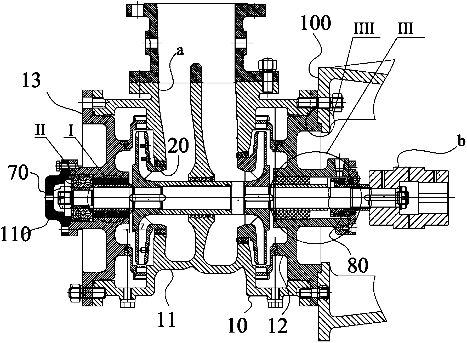
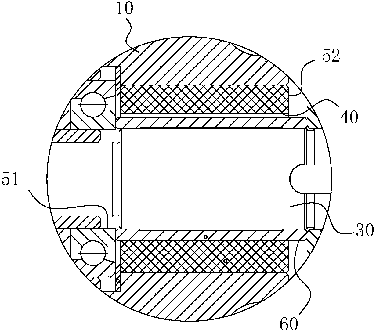
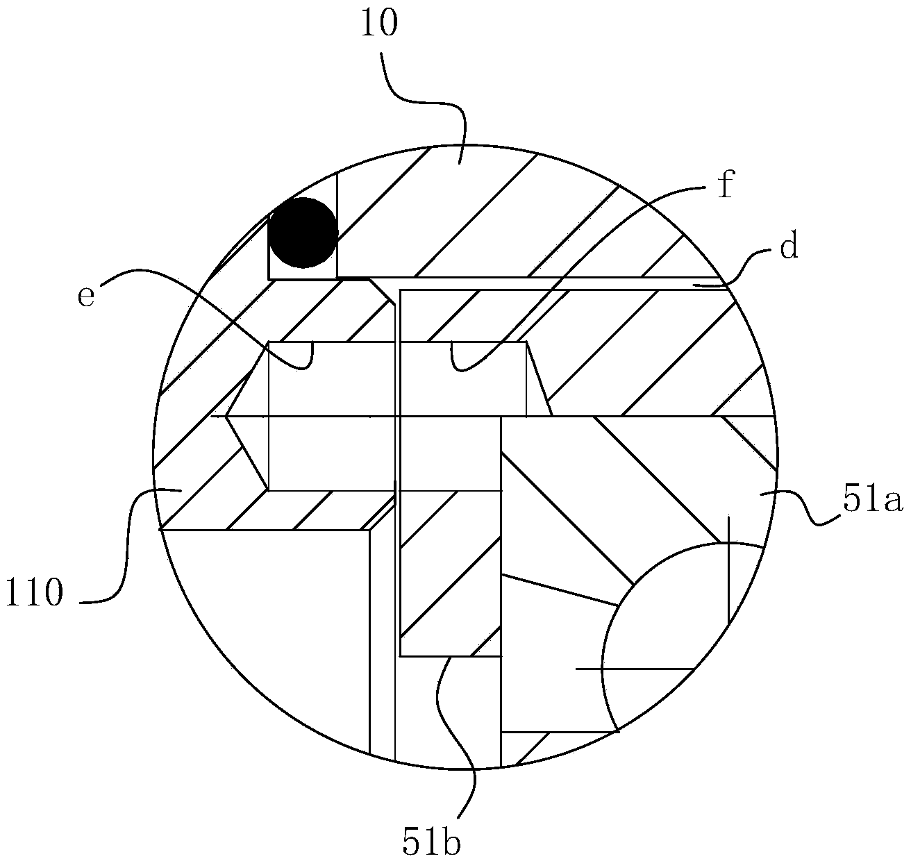
[0029] For ease of understanding, combined here Figure 1-5 Concrete components and workflow of the present invention are described as follows:

[0030] Centrifugal pumps under actual working conditions, such as Figure 1-5As shown, it is mainly assembled from the following components: the main base is composed of the pump body 11, and the pump chamber a is arranged in the pump body 11, and the pump shaft 30 is arranged through the pump chamber a, and the pump shaft 30 is from its right end to its left end Coupling b, connecting frame 100, mechanical seal assembly 80, drive end pump cover 12, auxiliary sliding bearing 53, secondary composite impeller and first stage composite impeller for forming pump impeller 20, non-drive end pump cover 13 are arranged accordingly , sliding bearing 52, rolling bearing 51, lock nut 70 and gland 110, the above components are assembled in sequence to form the whole centrifugal pump component. The pump body 11, the pump cover 12 at the driving...


PUM


Abstract

The invention belongs to the field of pump units, and particularly relates to a centrifugal pump with a self-lubricating bearing and a self-centering function. The centrifugal pump comprises a pump case, a pump impeller, a pump shaft and a driving source, wherein the pump impeller is used for driving a medium in the pump case to flow in a set direction, the pump shaft is used for driving the pump impeller to rotate, and the driving source is at least located at one end of the pump shaft and used for driving the pump shaft to rotate. A pump cavity is formed in the pump case and used for circulation of the medium, the pump shaft penetrates through a pump case body, and the pump impeller on the pump shaft is arranged to be contained in the pump cavity. The centrifugal pump further comprises a bearing assembly used for supporting the pump shaft, and a channel is formed between the position to be lubricated on the bearing assembly and the pump cavity and used for connecting the position to be lubricated and the pump cavity and for circulation of the medium. Liquid state fluidity of the medium self is used for achieving the self-lubricating effect of the bearing assembly, processing technologies of the centrifugal pump are reduced to the great degree, so that the effect of simplifying assembly structures of the centrifugal pump is achieved, and the centrifugal pump is simple in structure, good in stability and high in working reliability.

Description

technical field [0001] The invention belongs to the field of pump equipment, in particular to a centrifugal pump with a self-lubricating bearing and a self-centering function. Background technique [0002] The centrifugal pump is a device that transfers the mechanical energy of the prime mover to the liquid by means of the rotating suction of the impeller to the liquid. It is widely used in many fields such as petrochemical, agricultural irrigation, aerospace, and coal mines. On the one hand, as one of the important components of the centrifugal pump, the working performance of the bearing assembly directly affects the pump shaft of the centrifugal pump and its overall working ability; the bearing assembly is a component that is sleeved on the pump shaft to support the pump shaft. Traditional centrifugal pump bearing assemblies are mostly lubricated with oil or grease, and at the same time must have an independent bearing housing for fixing, which is described in the Chinese...

Claims


Application Information

Patent Timeline
IPC IPC(8): F04D29/06F04D29/046
Inventor 俞健柴立平胡敬宁李跃蔡标华石海峡秦子明何玉杰
Owner WUHAN HAIWANG TECH
Learn More