A constant force output air flotation device with guide rail following

A technology of constant force output and air flotation, which is applied in the direction of fluid pressure actuation devices, fluid pressure actuation system components, mechanical equipment, etc. Insufficient precision and other problems, to achieve the effect of no tracheal disturbance, high precision of constant force output, and good carrying capacity

Active Publication Date: 2015-12-16
南通盛净环保设备有限公司
View PDF1 Cites 0 Cited by
  • Summary
  • Abstract
  • Description
  • Claims
  • Application Information

AI Technical Summary

Problems solved by technology

[0004] Aiming at the problems in the existing constant force output device that the output force value is difficult to keep constant, the sensor measurement is not accurate enough, the constant force output accuracy is not high, and the long-distance constant force output cannot be realized, the present invention provides a stable, constant force output device. High-precision, constant force output air flotation device with guide rail following

Method used


Image

  • A constant force output air flotation device with guide rail following

Examples


Embodiment Construction

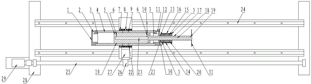
[0029] combine figure 1 , a constant force output air flotation device with guide rail following, including an output cylinder and a follower device; the follower device includes a slider, two linear guide rails 24, a motor 29, and a ball screw 25; the slider has two and is respectively sleeved on On the linear guide 24 , both ends of the linear guide 24 are supported by the support 28 , and the motor 29 is mounted on the support 28 and connected to the ball screw 25 .

[0030] The output cylinder includes a piston 5, a piston rod 17, a cylinder barrel 4, an end cover 1, a cylinder barrel cover 12, and an air intake sleeve. A connecting plate 27 is installed under the cylinder barrel 4, and the connecting plate 27 is fixedly connected with the two sliders. The lead screw 25 is connected to the connecting plate 27 through the nut seat 26 .

[0031] The piston 5 is sheathed in the cylinder barrel 4 and there is a very small gap between it and the wall of the cylinder barrel. Th...


PUM


Abstract

A constant-force-output air-floating device with the guide rail following function comprises an output air cylinder and a following device. The following device comprises a slider, a linear guide rail, a motor, a ball screw and a laser displacement sensor, wherein the linear guide rail is sleeved with the slider, and the motor is connected with the ball screw. The output air cylinder comprises a piston, a piston rod, a cylinder barrel, an end cover, a cylinder barrel cover and air inlet sleeves, wherein a connecting plate is installed below the cylinder barrel and is fixedly connected with the slider, the ball screw is connected with the connecting plate through a nut base, the piston rod is connected with the piston, the piston is arranged in the cylinder barrel in a sleeved mode, the two ends of the cylinder barrel are sleeved with the end cover and the cylinder barrel cover respectively, the piston rod penetrates through the cylinder barrel cover, the air inlet sleeves comprise the first air inlet sleeve and the second air inlet sleeve, the cylinder barrel is sleeved with the first air inlet sleeve, the cylinder barrel cover is sleeved with the second air inlet sleeve, and the laser displacement sensor is installed on the constant-force-output air cylinder. According to the constant-force-output air-floating device with the guide rail following function, constant force is output through the constant-force-output air cylinder, the output air cylinder is controlled to achieve long-distance motion through the following device, and the constant-force-output air-floating device is free of effects of disturbance of air pipes, good in stability and high in constant-force output accuracy.

Description

technical field [0001] The present invention relates to a constant force output device. Background technique [0002] According to its different application environments and application requirements, there are various structures and implementation methods for constant force output. Dynamic constant force output refers to loading a constant force value on the dynamically moving target workpiece. [0003] Hanging the target workpiece with weights is the simplest and most commonly used method of applying constant force. Since the weight of the weight is constant, the force acting on the target workpiece remains unchanged, but when the target workpiece accelerates or decelerates, the weight The weight will generate an additional force acting on the target workpiece due to the influence of its own inertial force, and the greater the mass of the weight, the greater the influence, so this method is only suitable for the occasion when the target workpiece moves at a low speed or a ...

Claims


Application Information

Patent Timeline
Patent Type & Authority Patents(China)
IPC IPC(8): F15B21/08F15B15/20F15B15/28
Inventor 孙建辉周丹锋
Owner 南通盛净环保设备有限公司
Why Eureka
Try Eureka