Combined clutch of automotive AMT (Automated Mechanical Transmission)

A combined clutch and automatic transmission technology is applied in the field of clutches to achieve the effects of improving driving safety, eliminating shifting shocks and reducing energy loss.

Inactive Publication Date: 2014-01-22
张耀新
View PDF5 Cites 5 Cited by
  • Summary
  • Abstract
  • Description
  • Claims
  • Application Information

AI Technical Summary

Problems solved by technology

[0004] The technical problem to be solved by the present invention is: to provide a combined clutch of an automobile AMT automatic transmission, to solve the problems such as the poor starting smoothness of the automobile and the impact of the shift caused by power interruption during the shifting process, and to overcome the deficiencies in the prior art

Method used


Image

  • Combined clutch of automotive AMT (Automated Mechanical Transmission)
  • Combined clutch of automotive AMT (Automated Mechanical Transmission)

Examples


Embodiment 1

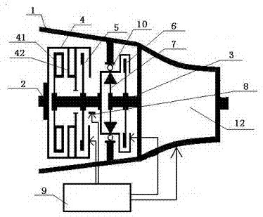
[0020] Embodiment 1: A combined clutch of an automobile AMT automatic transmission, comprising a housing 1, an engine power output shaft 2, a gear box input shaft 3, a fluid coupling 4 and a one-way clutch 7, the one-way clutch 7 The clutch 7 is installed on the input shaft 3 of the gear box through the bearing 10, and the power output shaft 2 of the engine is connected with the casing of the fluid coupling 4, that is, the power output shaft 2 of the engine is connected with the pump wheel I42 of the fluid coupling 4 The turbine I 41 of the fluid coupling 4 is connected to the outer ring of the one-way clutch 7 , and the inner ring of the one-way clutch 7 is connected to the input shaft 3 of the gear box. The fluid coupling 4 is equipped with a friction clutch A5 that can lock the pump wheel I42 and the turbine I41 of the fluid coupling 4 into one body. The friction clutch A5 is installed on the shell of the fluid coupling 4. The pressure plate of the friction clutch A5 is fix...

Embodiment 2

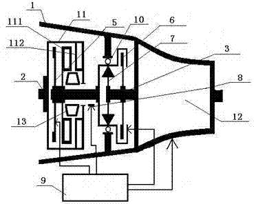
[0021] Embodiment 2: A combined clutch of an automobile AMT automatic transmission, including a housing 1, an engine power output shaft 2, a gear transmission input shaft 3, a hydraulic torque converter 11 with a locking device, and a one-way clutch 7 , the one-way clutch 7 is installed on the gear box input shaft 3 through the bearing 10, the locking device in the hydraulic torque converter 11 is controlled by the pressure oil provided by the oil pump, and the pressure oil An oil cooling device is installed in the pipeline, and the engine power output shaft 2 is connected to the casing of the torque converter 11, that is, the engine power output shaft 2 is connected to the pump wheel II 112 of the torque converter 11, and the The turbine II 111 of the hydraulic torque converter 11 is connected to the outer ring of the one-way clutch 7 , and the inner ring of the one-way clutch 7 is connected to the input shaft 3 of the gear box. The one-way clutch 7 is equipped with a frictio...


PUM


Abstract

The invention relates to a combined clutch of an automotive AMT (Automated Mechanical Transmission). The combined clutch of the automotive AMT comprises a housing, an engine power output shaft, a gear transmission input shaft, a hydraulic transmission device and a one-way clutch; the hydraulic transmission device is a hydraulic torque converter with a locking device or the hydraulic transmission device is a device which is formed by a hydraulic coupling and a friction clutch A; a pump wheel and a turbine of the hydraulic coupling can be locked into a whole through the friction clutch A; the engine power output shaft is connected with the hydraulic transmission device; the hydraulic transmission device is connected with the one-way clutch; the one-way clutch is connected with the gear transmission input shaft and provided with a friction clutch B; an inner ring and an outer ring of the one-way clutch can be locked into a whole through the friction clutch B. According to the combined clutch of the automotive AMT, an automobile can start smoothly, the problem that impact on shifting is caused by power interruption in the process of the shifting of the automobile is solved, the structure is simple, the cost is low, and the wide popularization and application can be convenient.

Description

technical field [0001] The invention relates to a clutch, in particular to a combined clutch of an automobile AMT automatic transmission. Background technique [0002] An automatic transmission with a microcomputer automatic shift device installed on the basis of a manual transmission car, referred to as AMT. Compared with other automotive automatic transmissions, AMT has the advantages of high transmission efficiency, fuel saving, simple structure, low production cost, and convenient maintenance. However, the biggest disadvantage of AMT is that it is extremely difficult to control the dry friction clutch, resulting in poor starting smoothness of the car, and the interruption of power during the shifting process causes shock (feeling of frustration) in shifting, which affects the ride comfort of the car and hinders Wide application of AMT. [0003] Although the currently disclosed patent No. "CN201443584" also uses a fluid coupling and a one-way clutch to solve the problem...

Claims


Application Information

Patent Timeline
Patent Type & Authority Applications(China)
IPC IPC(8): F16H47/06
CPCF16H45/02F16H2045/007F16H2045/0273
Inventor 张耀新
Owner 张耀新
Why Eureka
Try Eureka