Synchronous radiation X-ray diffraction in-situ stretching device and application method thereof

An in-situ stretching and X-ray technology, applied in measuring devices, using stable tension/pressure to test the strength of materials, instruments, etc., can solve the problem that the stretching device cannot be docked with the diffractometer, and achieve accurate and reliable test results. Accurately characterized, stable and controllable effects

Active Publication Date: 2014-01-22
INST OF METAL RESEARCH - CHINESE ACAD OF SCI
View PDF6 Cites 27 Cited by
  • Summary
  • Abstract
  • Description
  • Claims
  • Application Information

AI Technical Summary

Problems solved by technology

[0007] The purpose of the present invention is to provide a synchrotron radiation X-ray diffraction in-situ stretching device and its use method, so as to solve the problems that the conventional stretching device in the prior art cannot be docked with the diffractometer.

Method used


Image

  • Synchronous radiation X-ray diffraction in-situ stretching device and application method thereof
  • Synchronous radiation X-ray diffraction in-situ stretching device and application method thereof
  • Synchronous radiation X-ray diffraction in-situ stretching device and application method thereof

Examples


Embodiment 1

[0061] The stretching device of the present invention is on the Huber5021 type six-circle synchrotron radiation X-ray diffractometer, and the measurement method of synchrotron radiation X-ray diffraction in-situ stretching is applied to the Huber5021 type six-circle synchrotron radiation X-ray diffractometer, and the wavelength is 0.12396nm. Equally with Fe-13%Cr-4%Ni (weight percent) martensitic stainless steel as experimental object, this method is carried out as follows:

[0062] 1) The sample is machined into a 14mmX43mmX0.5mm plate-shaped stretched part, the surface of the sample is ground and then mechanically polished, and then electrolytic polishing is performed to eliminate the stress layer on the surface of the stretched part;

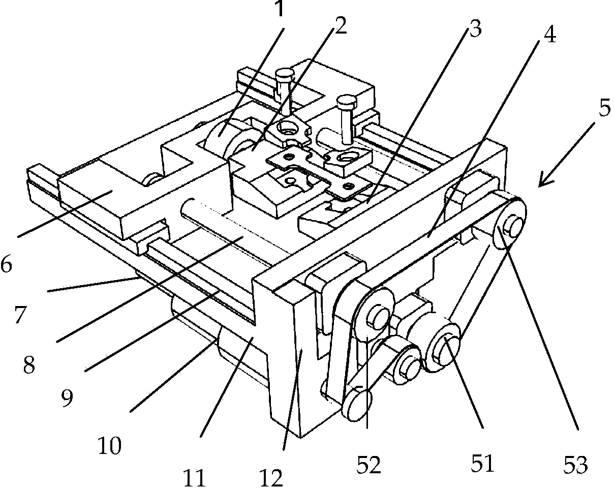
[0063] 2) When the rear sample loading jig 2 is adjusted to a distance of 45mm from the front sample fixing jig 3 through the computer operating system, fix the two ends of the tensile sample 18 on the front sample fixing jig 3 and the rear sa...

Embodiment 2

[0071] The laboratory X-ray diffraction in-situ tensile measurement method is applied to the Japanese Rigaku D / max-2500PC X-ray diffractometer. The wavelength of the copper target is selected to be 0.15418nm, and Fe-13%Cr-4%Ni (weight percentage) Ma Tensitic stainless steel is used as the experimental object, and the method is carried out as follows:

[0072] 1) The sample is machined into a 14mmX43mmX0.5mm plate-shaped stretched part, the surface of the sample is ground and then mechanically polished, and then electrolytic polishing is performed to eliminate the stress layer on the surface of the stretched part;

[0073] 2) Start the computer operating system, move the rear sample loading fixture 2, adjust the distance between it and the front sample fixing fixture 3 to be 35 mm, and fix the two ends of the tensile sample 18 on the front sample fixing fixture 3 and the rear sample loading fixture 2. , and press the fixing gasket 17, and lock it with the locking screw 19, at t...


PUM


Abstract

The invention relates to the field of material structure research and performance in-situ test, and specifically relates to a synchronous radiation X-ray diffraction in-situ stretching device and an application method thereof. The device comprises three main components of a loader, a driver, and a fixing support. The loader is mainly manufactured by using high-strength aluminum alloy or titanium alloy, and comprises a pedestal, a load driving part, a load transmission part, a sample fixture part, a stretch sensor part, and a slide guide rail part. The driver is an integration of a data collection card and a motor driver, and is independent from the loader. The fixing support is manufactured from high-strength aluminum alloy, and has a detachable interface on the lower part. The device is designed based on an X-ray reflective optical path principle. Sample loading fixture and load sensor heights satisfy requirements. The device can be effectively applied in in-situ microstructure and performance integral tests. With the device, a dynamic process of stress and strain distribution of various phases of a material can be subjected to in-situ observation by using high-energy X-rays, and material mechanical performance mechanism can be analyzed on a micro-phase size.

Description

technical field [0001] The invention relates to the field of material structure research and performance in-situ testing, in particular to a synchrotron radiation X-ray diffraction in-situ stretching device and a use method thereof. A device installed in a synchrotron radiation X-ray diffractometer is used to conduct in-situ dynamic mechanical properties and microscopic stress-strain distribution tests and deformation-induced phase transition observations of various solid materials, and to study the microscopic properties of materials according to the changes in material X-ray diffraction characteristics. The uneven distribution of stress / strain on the scale provides the possibility to study the properties of each component phase of the material on the phase scale, breaking the limits of traditional research methods. Background technique [0002] The mechanical properties of materials refer to the mechanical response of materials in different working environments from the be...

Claims


Application Information

Patent Timeline
Patent Type & Authority Applications(China)
IPC IPC(8): G01N3/08G01N3/06
Inventor 王培张盛华邓江宁李殿中李依依
Owner INST OF METAL RESEARCH - CHINESE ACAD OF SCI
Why Eureka
Try Eureka