Supercharge Your Innovation With Domain-Expert AI Agents!

Method and system for realizing fault joint switching device model of power system

A power system and model realization technology, applied in general control systems, control/regulation systems, simulators, etc., can solve the problems of difficult operation and management, lack of a fault linkage control strategy model, and a large workload of the fault linkage control strategy. and other problems to achieve the effect of reducing the computational workload

Active Publication Date: 2014-01-22
POWER DISPATCHING CONTROL CENT OF GUANGDONG POWER GRID CO LTD
View PDF5 Cites 8 Cited by
  • Summary
  • Abstract
  • Description
  • Claims
  • Application Information

AI Technical Summary

Problems solved by technology

Since the current power system analysis and simulation software does not have a fault-connected control strategy model, and the fault-connected devices are highly targeted, have a variety of types, and have complex control logic and functions, the fault-connected control strategy is basically obtained through manual calculation and analysis. of
Therefore, the compilation of the fault joint switching control strategy is not only a large workload, but also difficult to accurately analyze and evaluate the dynamic characteristics of the corresponding devices and their impact on the power grid
In addition, it also brings problems such as device reliability, difficulty in adaptability verification, and difficulty in operation management.

Method used


Image

  • Method and system for realizing fault joint switching device model of power system
  • Method and system for realizing fault joint switching device model of power system
  • Method and system for realizing fault joint switching device model of power system

Examples


Embodiment Construction

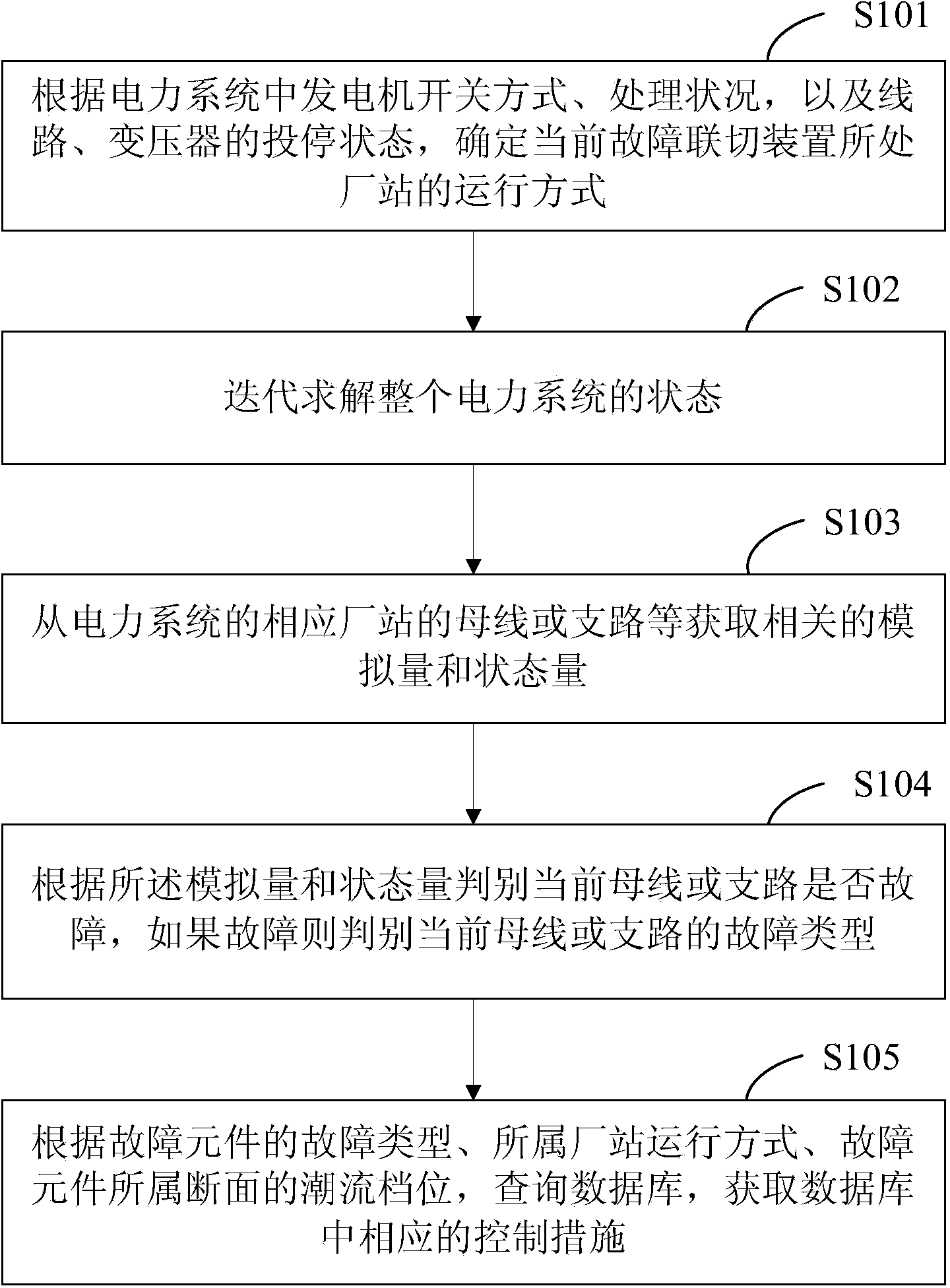
[0023] see figure 1 , figure 1 It is a schematic diagram of the realization method of the power system fault coupling device model of the present invention.

[0024] The method for implementing the power system fault coupling device model includes the following steps:

[0025] S101, according to the generator switching mode and processing status in the power system, as well as the switching and stopping status of the line and transformer, determine the current operation mode of the power station where the fault switching device is located;

[0026] S102, iteratively solving the state of the entire power system;

[0027] S103, obtaining relevant analog and state quantities from the busbar or branch of the corresponding plant of the power system;

[0028] S104, judging whether the current bus or branch is faulty according to the analog quantity and state quantity, and if so, judging the fault type of the current bus or branch;

[0029] S105. According to the fault type of th...


PUM


Abstract

The invention provides a method and a system for realizing a fault joint switching device model of a power system. The method comprises the following steps: determining the running mode of a station at which the current fault joint switching device is located according to the On / Off mode and the processing state of a power generator and the work and stop states of circuits and a transformer in the power system; solving the state of the whole power system in an iterating way; acquiring corresponding analog quantity and state quantity from the bus, or the branch circuit and the like of the corresponding station of the power system; judging whether the current bus or branch circuit fails or not according to the analog quantity and the state quantity, and judging the fault type of the current bus or the branch circuit if a fault occurs; according to the fault type of a fault element, the running mode of the corresponding station and the current gear of a cross section on which the fault element is located, searching a database, acquiring a corresponding control means in the database and inserting the action information of the corresponding control means in an event queue. The action behavior and the control properties of various fault joint switching devices in the power system can be accurately simulated.

Description

technical field [0001] The invention relates to the technical field of power system reliability control, in particular to a method for realizing a model of a power system fault coupling device and a system thereof. Background technique [0002] With the continuous expansion of the scale of the power grid and the increasingly complex structure, there are more and more AC transmission channels or AC-DC parallel transmission channels for centralized power transmission across regions. The adoption of new power transmission technologies makes the operating characteristics of the power grid more and more complicated. The security defense system of the country has been severely challenged. Due to the unbalanced development of load and power supply, the power transmission between regional power grids is increasing day by day, and chain reactions are prone to occur in various accidents, resulting in huge economic losses. As one of the effective means to prevent large-scale power out...

Claims


Application Information

Patent Timeline
IPC IPC(8): G05B17/02
Inventor 钱峰陈兴华吴国炳杨文佳杨银国魏宏谭伟王延纬刘通段秦刚
Owner POWER DISPATCHING CONTROL CENT OF GUANGDONG POWER GRID CO LTD
Features
  • R&D
  • Intellectual Property
  • Life Sciences
  • Materials
  • Tech Scout
  • Unparalleled Data Quality
  • Higher Quality Content
  • 60% Fewer Hallucinations
Learn More