
Auxiliary power monitoring system

A monitoring system, a technology for factory power consumption, applied in the directions of comprehensive factory control, comprehensive factory control, electrical program control, etc., can solve the problems of inability to process information in time to make electrical equipment run, increase costs for enterprises, and information time difference, etc., to ensure communication. The timeliness, reduce investment, reduce the effect of cable laying

Active Publication Date: 2014-01-22
CHINA ENERGY ENG GRP GUANGDONG ELECTRIC POWER DESIGN INST CO LTD
View PDF7 Cites 5 Cited by
  • Summary
  • Abstract
  • Description
  • Claims
  • Application Information

AI Technical Summary

Problems solved by technology

[0003] There are a lot of electrical equipment in the power plant, and the amount of information is large. During the data transmission process, it is easy to cause data congestion and system collapse. The general plant power monitoring system not only undertakes the monitoring background work of electrical equipment, but also communicates with the DCS system (distributed control system) , but also communicate with the SIS system (factory-level monitoring information system) and other external systems. There is a time difference between the information obtained by different systems, and the failure to process the information in time will cause greater risks in the operation of electrical equipment.
The general factory electricity monitoring system includes electrical engineer station and DCS system engineer station. The operating status of electrical equipment and corresponding processing, which caused repeated configuration of the electrical engineer station and the DCS system engineer station, which increased costs for the enterprise

Method used


Image

  • Auxiliary power monitoring system

Examples


Embodiment Construction

[0016] Embodiments of the present invention are described in detail below in conjunction with accompanying drawings:

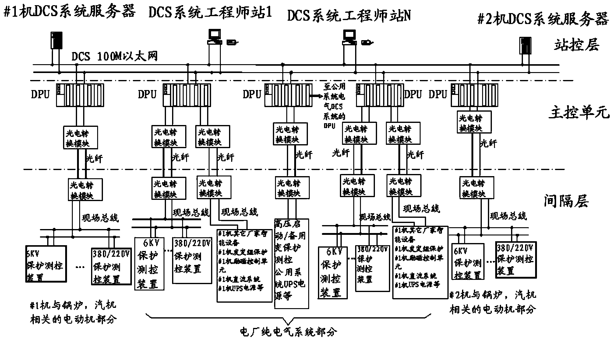
[0017] refer to figure 1 In an embodiment of the present invention, the factory power monitoring system includes a station control layer, a main control unit, and an interval layer. The station control layer includes a DCS system server and a DCS system engineer station. The DCS system server and the DCS system engineer station are connected The main control unit layer includes the DPU of the DCS system, and the interval layer includes the protection measurement and control device. The protection measurement and control device is connected to the field bus. One end of the DPU is connected to the Ethernet, and the other end is connected to the field bus. , the Ethernet is 100M Ethernet.

[0018] The DPU is connected to the field bus through an optical fiber, and a photoelectric conversion module is arranged between the optical fiber, the field bus and the DPU....


PUM


Abstract

The invention discloses an auxiliary power monitoring system comprising a station control layer, a master control unit and a spacer layer. The station control layer comprises a DCS system server and a DCS system engineer station. The DCS system server and the DCS system engineer station are both accessed to an Ethernet. The master control unit layer comprises DPUs of a DCS system. The spacer layer comprises a protection and monitoring device which is accessed to an onsite bus. One end of each DPU is accessed to the Ethernet, and the other end is accessed to the onsite bus. The spacer layer and the DPUs of the master control unit layer are communicated directly so that communication time is shortened and timeliness of communication is ensured. The system is directly monitored via the DCS system engineer station, and an electrical engineer station is eliminated so that investment of devices is reduced, laying of cables is reduced, cost is saved, a conventional networking structure of adopting an electrical monitoring system and the DCS system to operate electrical devices simultaneously is changed, direct monitoring of the DCS system towards an auxiliary power system is realized and communication efficiency is enhanced.

Description

technical field [0001] The invention relates to an electricity monitoring system, in particular to a utility electricity monitoring system. Background technique [0002] The plant power monitoring system is a system that realizes the management, monitoring, and data storage of the plant power system. The plant power system occupies a very important position in the production and daily operation of the power plant. Its safe operation directly affects the safety of the power plant. production and economic efficiency. The plant power monitoring system is the key to ensure the normal and safe operation of the plant power system. [0003] There are a lot of electrical equipment in the power plant, and the amount of information is large. During the data transmission process, it is easy to cause data congestion and system collapse. The general plant power monitoring system not only undertakes the monitoring background work of electrical equipment, but also communicates with the DC...

Claims


Application Information

Patent Timeline
IPC IPC(8): G05B19/418
CPCY02P90/02
Inventor 冷祥彪刘宇穗李煜东汪少勇杨莉谭江平谢创树
Owner CHINA ENERGY ENG GRP GUANGDONG ELECTRIC POWER DESIGN INST CO LTD
Learn More