Resonator

A resonator and resonant cavity technology, which is applied in the direction of resonators, waveguide devices, electrical components, etc., can solve problems such as poor contact between the resonant column and the resonant cavity, poor electrical conductivity, and fastening failure between the resonant column and the resonant cavity. Achieve the effect of eliminating poor contact and increasing the contact area

Inactive Publication Date: 2014-01-22
PIVOTONE COMM TECH
View PDF4 Cites 1 Cited by
  • Summary
  • Abstract
  • Description
  • Claims
  • Application Information

AI Technical Summary

Problems solved by technology

Although this method can be used to realize the connection between the lower end of the resonant column and the bottom of the resonant cavity, this connection method is greatly affected by the flatness, roughness and screw locking force of the lower end surface of the resonant column. Poor contact, poor electrical conductivity and other hidden dangers
And because the connection between the resonant column and the resonant cavity is realized close to a screw, once the screw slips, it will cause the fastening failure between the resonant column and the resonant cavity. Therefore, the reliability of this connection is poor

Method used


Image

  • Resonator

Examples


Embodiment Construction

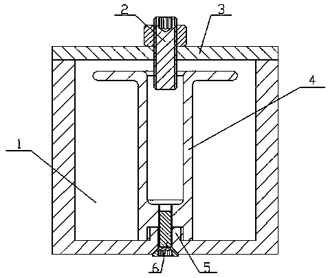
[0010] Such as figure 1 As shown, the resonator of the present invention includes a resonant cavity 1 , a cover plate 3 is fixed at the mouth of the resonant cavity 1 , and a resonant post 4 is arranged between the cover plate 3 and the cavity bottom of the resonant cavity 1 . A screw hole is processed on the cover plate 3 opposite to the upper end of the resonant column 4 , and a tuning screw 2 is screwed in the screw hole, and the inner end of the tuning screw 2 extends into the upper end of the resonant column 4 . The center of the cavity bottom of the resonance cavity 1 is processed with a cylindrical upper protrusion 5, and the cylindrical upper protrusion 5 is integrated with the cavity bottom of the resonance cavity 1, and the lower end of the resonance column 4 is processed with a The circular upper pit corresponding to the cylindrical upper protrusion 5, the diameter of the circular upper pit matches the diameter of the cylindrical upper protrusion 5, and the inner wa...


PUM


Abstract

The invention relates to a resonator. The resonator comprises a resonant cavity, wherein a cover plate is arranged at an opening of the resonant cavity, and a resonant column is arranged inside the resonant cavity. A screw hole is formed in the cover plate opposite to the upper end of the resonant column, and a resonant screw is arranged inside the screw hole. The resonator is characterized in that an upper cylindrical bulge is arranged at the center of the bottom of the resonant cavity, an upper round pit is formed in the lower end of the resonant column, threads are formed on both the inner wall of the round pit and the outer side surface of the upper cylindrical bulge through machining, and the upper cylindrical bulge is screwed in the round pit. Screw holes with identical diameters are formed in the center of the bottom of the resonant cavity, the center of the upper cylindrical bulge and the center of the lower end of the resonant column, a fastening screw is arranged inside the screw holes, and the front end of the fastening screw is screwed in the screw holes at the center of the bottom of the resonant cavity, the center of the upper cylindrical bulge and the center of the lower end of the resonant column sequentially, so that the lower end of the resonant column and the bottom of the resonant cavity are matched closely. With the adoption of the resonator, the fastening reliability between the resonant column and the resonant cavity can be improved. The resonator is applicable to communication equipment of a wireless base station.

Description

technical field [0001] The invention relates to a resonator. Specifically, it is a resonator installed on the communication equipment of the wireless base station to filter out harmonics. Background technique [0002] It is known in the field of wireless communication that with the rapid development of wireless communication systems, including the establishment and promotion of third-generation and fourth-generation communication systems in recent years, the quality requirements for communication systems are constantly improving, especially for different systems and frequency bands. The interference suppression requirements are getting higher and higher, and the requirements for the passive intermodulation index of the key device in the communication system---the radio frequency filter are particularly strict, because passive intermodulation refers to the passive intermodulation when the passive device injects a high-power signal The case introduces distortion of an input s...

Claims


Application Information

Patent Timeline
Patent Type & Authority Applications(China)
IPC IPC(8): H01P7/06H01P1/212
Inventor 林超宋永民
Owner PIVOTONE COMM TECH
Why Eureka
Try Eureka