Low-profile high-gain panel antenna and application thereof

A flat-panel antenna, high-gain technology, applied in slot antennas, antenna supports/installation devices, radiating element structures, etc. The effect of small thickness

Inactive Publication Date: 2014-01-22
SHANDONG GUOWEI SATELLITE COMM
View PDF9 Cites 9 Cited by
  • Summary
  • Abstract
  • Description
  • Claims
  • Application Information

AI Technical Summary

Problems solved by technology

Although the radiation efficiency of panel antennas is much higher than other types of antennas, the efficiency of panel antennas commonly used in the market today is between 75% and 80%, and the thickness is relatively large: generally above 28mm, and its efficiency and portability exist. insufficient

Method used


Image

  • Low-profile high-gain panel antenna and application thereof
  • Low-profile high-gain panel antenna and application thereof
  • Low-profile high-gain panel antenna and application thereof

Examples


Embodiment 1

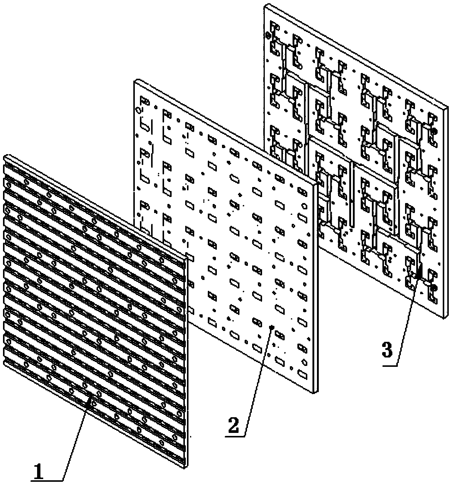
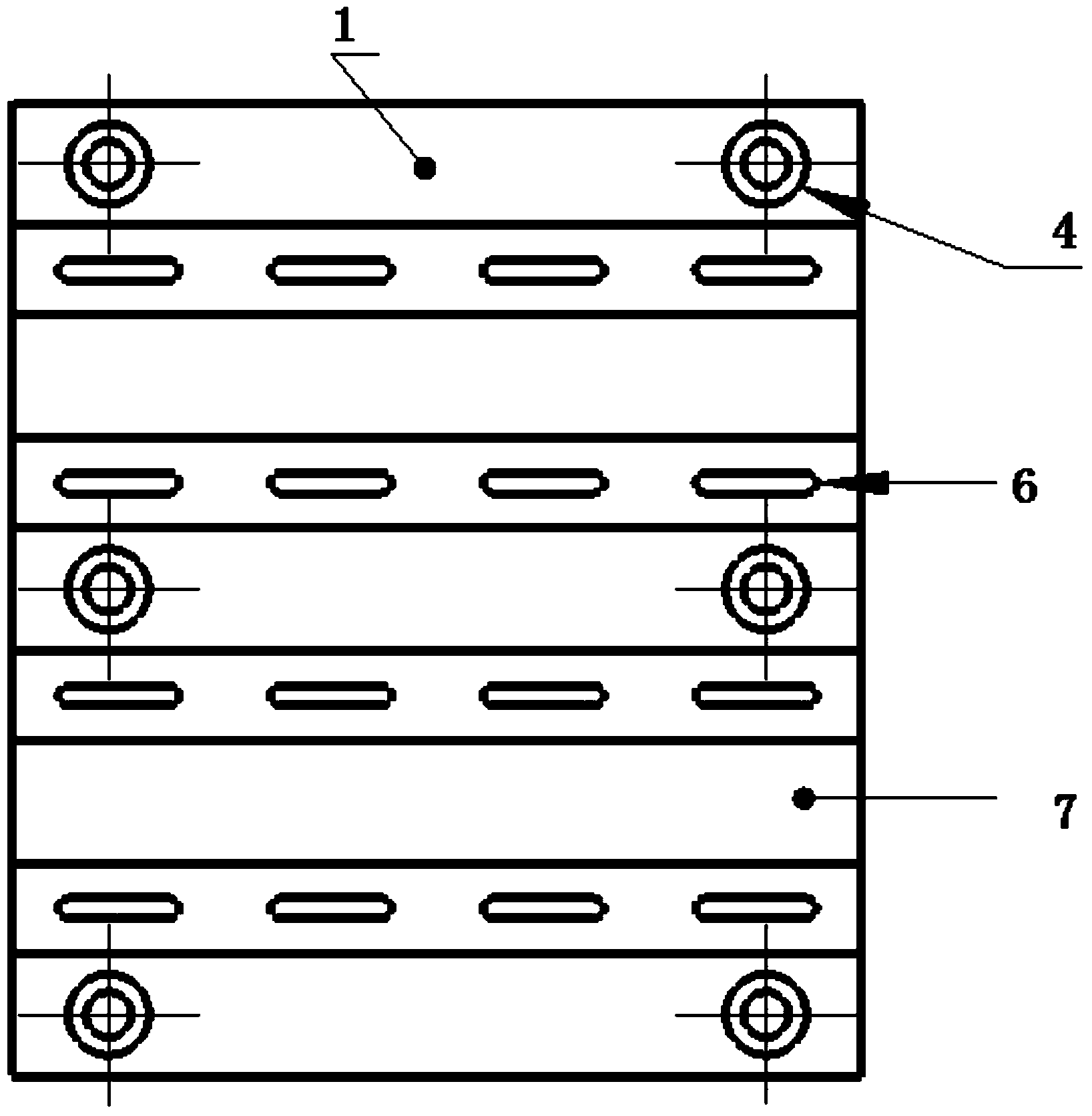
[0033] A low-profile high-gain panel antenna, including a radiation layer 1, a coupling layer 2 and a feed layer 3; the radiation layer 1 is a slot radiation layer: a radiation slot 6 is arranged on the radiation layer 1, and the radiation slot The length of 6 is half of the average wavelength of the Ku band.

Embodiment 2

[0035] A low-profile high-gain panel antenna as described in Embodiment 1, the difference is that the low-profile high-gain panel antenna has a thickness of 19-22 mm.

Embodiment 3

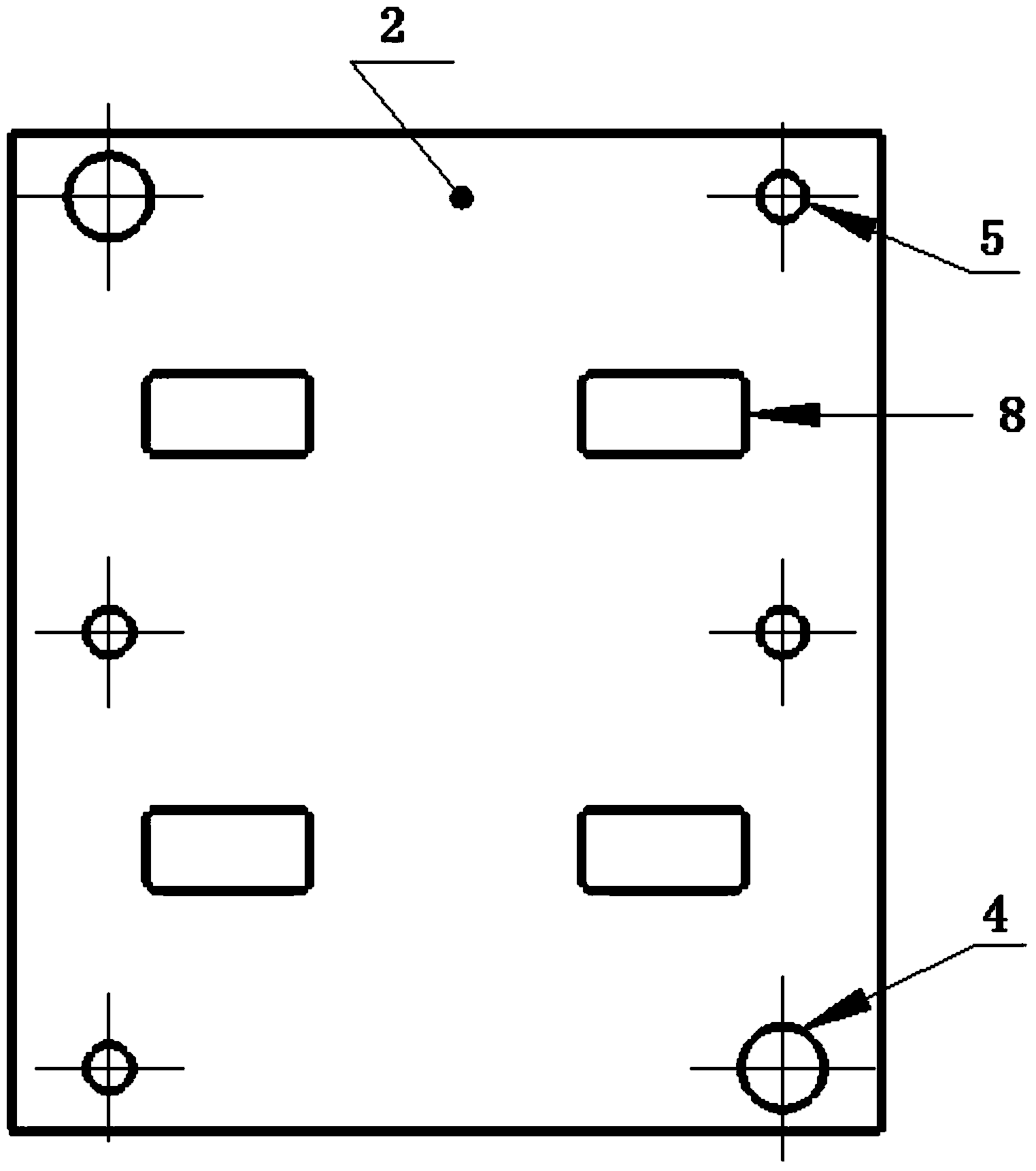
[0037] A low-profile high-gain panel antenna as described in Embodiments 1 and 2, the difference is that the radiation layer 1, the coupling layer 2 and the feeding layer 3 are fixed and installed in sequence through the positioning hole 4, the connecting hole 5 and the screw matching sequence .

[0038] The slit length of the radiating slit 6 is 11-13mm, and the slit width of the radiating slit 6 is 1.7-2.2mm.

[0039] Multiple coupling units are arranged on the coupling layer 2 , wherein a single coupling unit includes four coupling cavities 8 .

[0040] The feed layer 3 includes a plurality of feed units, the single feed unit corresponds to the coupling unit, the single feed unit includes a feed waveguide 9 and a power splitter 10, and adopts a waveguide T-branch matching method , a capacitive resistance step 12 is set at the joint of the feeding waveguide 9 .

[0041] The size of the feeding waveguide 9 is a=13.2mm, b=6.6mm.

[0042] The side length of the capacitive re...


PUM


Abstract

The invention relates to a low-profile high-gain panel antenna which comprises a radiation layer, a coupling layer and a feed layer, wherein the radiation layer is a slit radiation layer; radiation slits are arranged on the radiation layer; the length of each radiation slit is one half of the mean wavelength of a Ku wave band; the feed layer comprises a plurality of feed units; each single feed unit corresponds to a coupling unit and comprises a feed waveguide and a power splitter; and a waveguide T branch matching manner is adopted, and one capacitive resistance stair is arranged at a joint of each feed waveguide. According to the low-profile high-gain panel antenna, the efficiency of the antenna is improved to more than 85%, and the overall thickness of the antenna is reduced to about 21 mm; and on the basis that the efficiency of the antenna is guaranteed, the thickness of the antenna is greatly reduced, so that the size of the panel antenna is smaller, and the weight is lower. The low-profile high-gain panel antenna has the characteristics of low profile, high efficiency and the like.

Description

technical field [0001] The invention relates to a low-profile high-gain planar antenna and its application, belonging to the technical field of communication planar antennas. Background technique [0002] Due to the advantages of small size, light weight, high efficiency and easy installation, flat panel antennas are increasingly used in high-efficiency satellites, aircraft, and mobile communication phones. The bandwidth of the panel antenna is relatively narrow, and the narrow bandwidth transmission of confidential materials is very suitable for state secrets or military applications, and the panel antenna is easy to combine with high-frequency front-end modules, which is very suitable for wireless mobile communication systems. Although the radiation efficiency of panel antennas is much higher than other types of antennas, the efficiency of panel antennas commonly used in the market today is between 75% and 80%, and the thickness is relatively large: generally above 28mm, a...

Claims


Application Information

Patent Timeline
Patent Type & Authority Applications(China)
IPC IPC(8): H01Q1/36H01Q1/22H01Q13/10
Inventor 周玲玲吴超杨猛
Owner SHANDONG GUOWEI SATELLITE COMM
Why Eureka
Try Eureka