
Manipulator taking mechanism

A technology of reclaiming mechanism and manipulator, applied in metal processing equipment, feeding device, stripping device, etc., can solve the problems of rising labor costs, and achieve the effects of stable power output, reduced production cost, and simple structure

Inactive Publication Date: 2014-01-29
YIHE PRECISION IND SUZHOU
View PDF7 Cites 24 Cited by
  • Summary
  • Abstract
  • Description
  • Claims
  • Application Information

AI Technical Summary

Problems solved by technology

However, the rising labor cost in recent years has forced enterprises to consider how to replace manual operations with mechanical retrieving. The introduction of reclaiming manipulators has avoided the above problems

Method used


Image

  • Manipulator taking mechanism
  • Manipulator taking mechanism
  • Manipulator taking mechanism

Examples


Embodiment 1

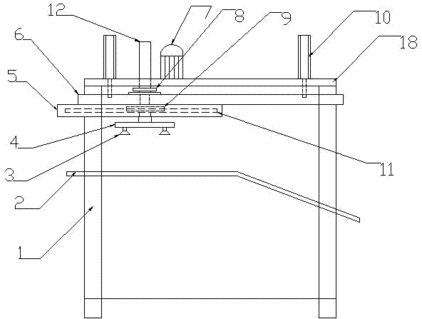
[0029] A manipulator retrieving mechanism is used for retrieving and conveying stamping parts between two stamping equipment, including a frame 1, a retrieving vertical moving device, a retrieving horizontal moving device, a retrieving device and an electric control device.

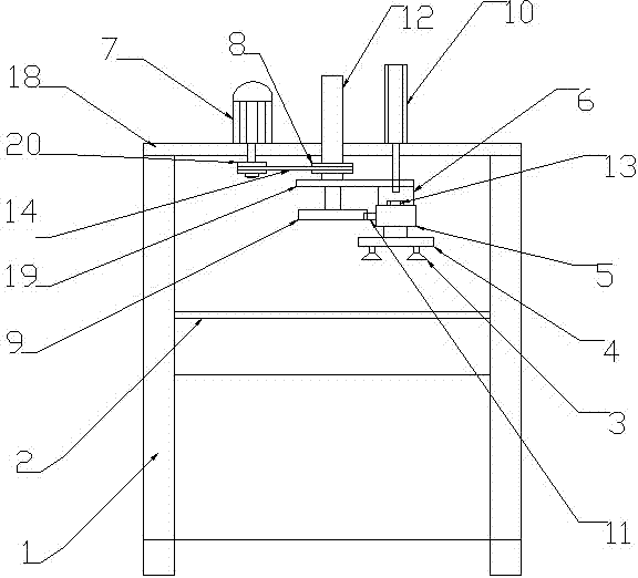
[0030] like Figure 1-2 As shown, the frame 1 includes a support base and a fixed platform 18 arranged above the support base. The frame 1 also includes an intermediate platform 2 arranged in the middle of the frame for the transfer channel of the stamping parts between the two punching machines. The inclined platform, the horizontal platform and the inclined platform are fixedly connected.

[0031] The vertical moving device for taking materials comprises a horizontally arranged first profile support 6 and a cylinder 10 for driving the first profile support 6 to move vertically. The cylinder 10 is fixedly arranged on a fixed platform 18. The support 6 is fixedly connected and drives the first profile s...

Embodiment 2

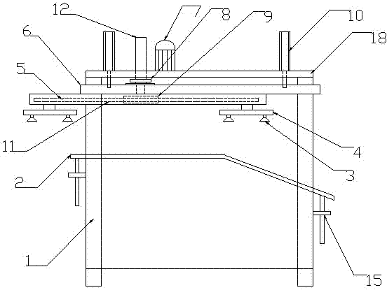
[0040] The rest are the same as in Embodiment 1, the difference is that the vertical movement drive device also includes a vertical guide assembly, the vertical guide assembly includes a guide seat and a guide rod fixedly arranged on the fixed platform, the guide seat is provided with a through hole in the vertical direction, and the guide The rod slides through the through hole and is fixedly connected with the first profile bracket.

[0041] Under the action of the vertical guide assembly, the reclaiming device has a clear direction and reliable movement when retrieving materials.

[0042] The second profile support is arranged in parallel with the first profile support and is slidably connected through the pulley slide rail.

Embodiment 3

[0044] The rest is the same as that of Embodiment 2, except that when the product size is large, the reclaiming device can be provided with two or more adsorption member brackets.

[0045] Setting more than two adsorption component brackets can simultaneously absorb the head and tail parts of the stamping parts, shorten the transmission stroke during the transmission process, increase the transmission speed, and reduce the size of the entire manipulator retrieving mechanism at the same time.


PUM


Abstract

A manipulator taking mechanism comprises a frame, a taking vertical-movement device, a taking horizontal-movement device, a taking device, and an electric control device, wherein the frame comprises a support base and a fixed platform disposed above the support base, the taking vertical-movement device comprises a horizontal first profile support and a vertical movement drive device, the taking horizontal-movement device comprises a horizontal second profile support and a horizontal movement drive device, the taking device comprises an adsorption component and an adsorption component support, the adsorption component support is fixedly connected with the second profile support, the electric control device comprises a sensor, a PLC and a servo driver, and the sensor, the PLC and the servo driver are connected through electrical signals. The manipulator taking mechanism is used for taking and conveying stamping parts after the parts are machined on a punch press; during material taking, the electric control device servo-drives an adsorption device to horizontally move in place and servo-drives adsorption device to adsorb a product; actions are organically harmonized; operating time and labor cost are reduced.

Description

technical field [0001] The invention relates to a mechanical conveying device, in particular to a manipulator retrieving mechanism for retrieving and conveying stamped parts of a punch press. Background technique [0002] With the improvement of living standards, users have increasing requirements for product diversification. For most manufacturers, the production of products with multiple varieties and small batches is more and more popular among customers. However, this kind of small-batch products with the size of stamping parts above 300*300 and below 1200*1200, because the products only need to be transferred between fewer processing equipment, is not suitable for the batch production line of the stamping factory. Automated manufacturing. If a complete manipulator device is used, the production cost will be greatly increased. At the same time, the manipulator adjustment time is relatively long, and sometimes the adjustment time may be longer than the production time. ...

Claims


Application Information

Patent Timeline
IPC IPC(8): B21D43/18B21D45/00
Inventor 潘小军赵鹏赵小波秦响沈克雨
Owner YIHE PRECISION IND SUZHOU
Features
  • Generate Ideas
  • Intellectual Property
  • Life Sciences
  • Materials
  • Tech Scout
  • Unparalleled Data Quality
  • Higher Quality Content
  • 60% Fewer Hallucinations
Learn More