Proceeding self-locking device

A self-locking device and self-locking technology, applied in the field of mobile machinery accessories, can solve the problems of inability to achieve slope position locking, inability to achieve heavy load, insufficient reliability, etc., and achieve the effects of simple structure, simplified equipment, and reliable equipment

Inactive Publication Date: 2014-01-29
JILIN UNIV
View PDF5 Cites 3 Cited by
  • Summary
  • Abstract
  • Description
  • Claims
  • Application Information

AI Technical Summary

Problems solved by technology

[0003] The purpose of the present invention is to provide a traveling self-locking device to solve the problem of serious wear of brake pads, insufficient reliability, short service life, inability to realize heavy load, Problems with inability to achieve ramp position lock

Method used


Image

  • Proceeding self-locking device
  • Proceeding self-locking device
  • Proceeding self-locking device

Examples


Embodiment Construction

[0043] The present invention will be described in further detail below in conjunction with embodiment.

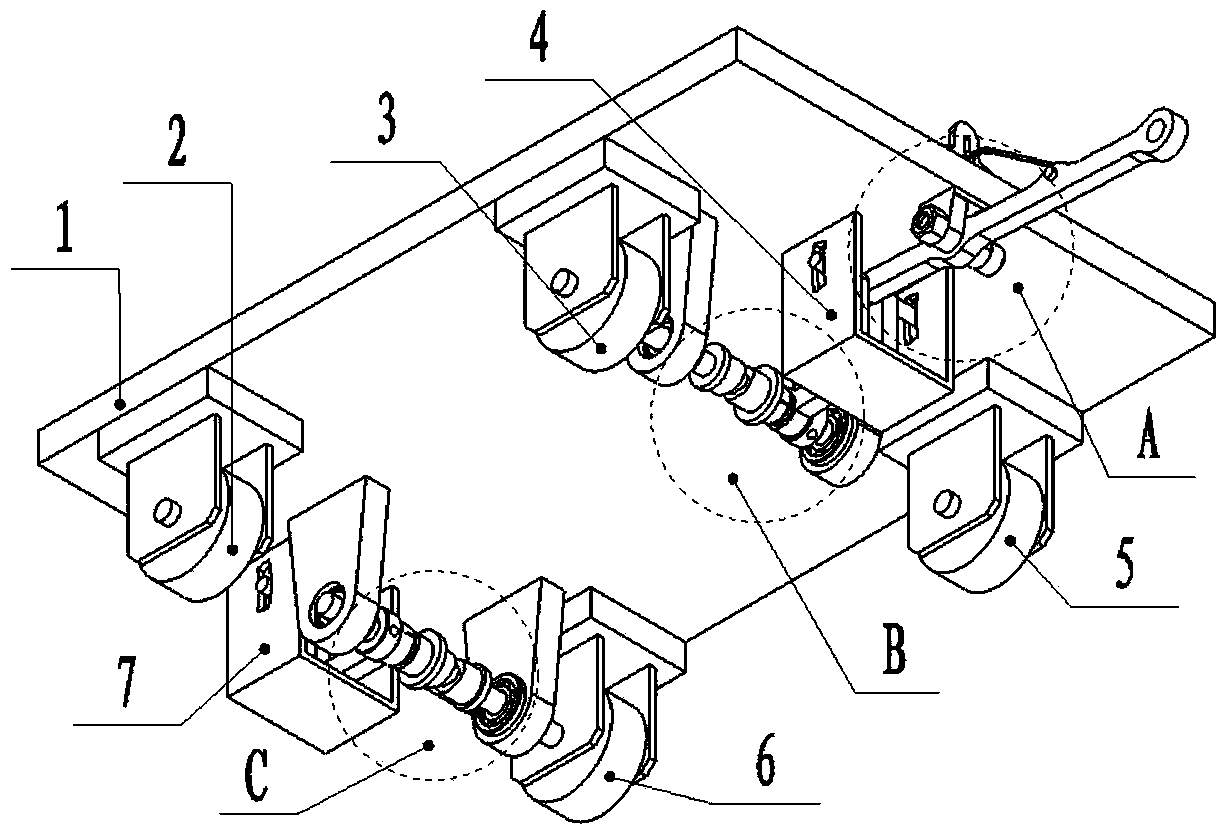
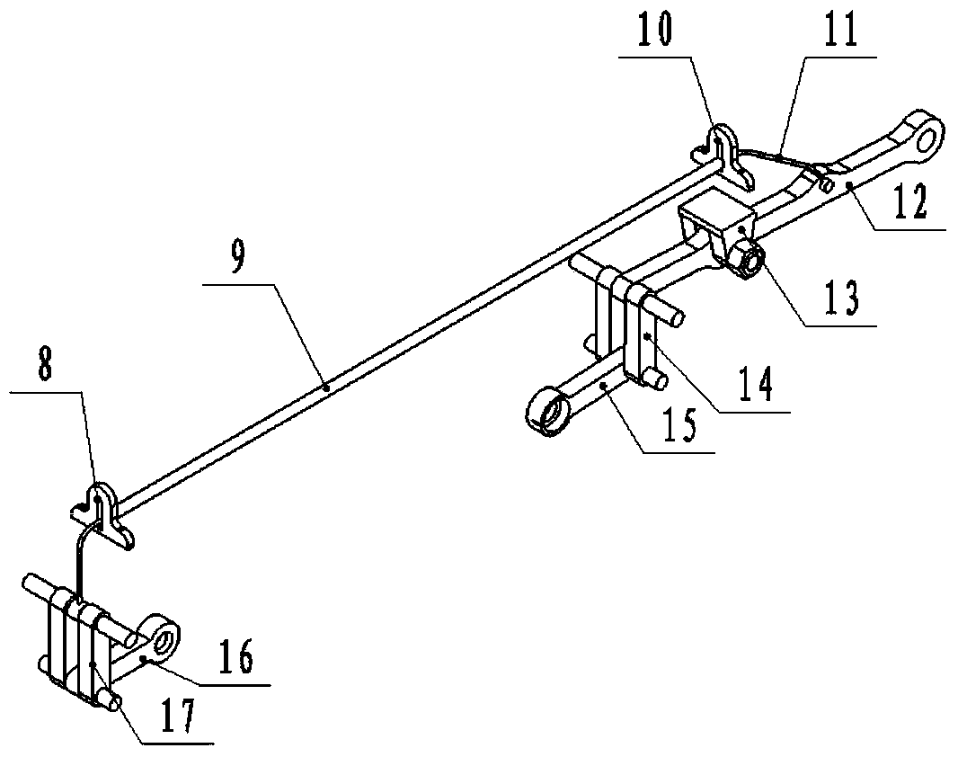
[0044] The present invention is mainly realized through the following technical solutions: a traveling self-locking device, which consists of a transmission system A, a self-locking clutch system I B, a self-locking clutch system II C, a fuselage bottom plate 1, a left front wheel 2, a left rear wheel 3, Connecting piece limiting frame Ⅰ4, right rear wheel 5, right front wheel 6, connecting piece limiting frame Ⅱ7, connecting rod Ⅰ14, connecting piece Ⅰ15, connecting piece Ⅱ16 and connecting rod Ⅱ17, of which left front wheel 2, left rear wheel 3. The right rear wheel 5 and the right front wheel 6 are fixedly connected to the four corners of the bottom surface of the fuselage bottom plate 1 via respective brackets respectively.

[0045] The hinge support 13 in the transmission system A of this embodiment is fixedly connected to the front part of the center line of the botto...


PUM


Abstract

A proceeding self-locking device belongs to the technical field of accessories of mobile machinery. Four wheels are fixedly connected onto four corners of the bottom surface of a machine body base plate through a support respectively, a hinged supporting seat I is fixedly connected onto the front portion of the bottom surface of the machine body base plate, two steel wire soft rope limit seats are respectively fixedly connected onto the front end and the rear end of the top surface of the machine body base plate, the front end and the rear end of a steel wire soft rope are fixedly connected a connecting rod II and a control rod respectively, the left end of a main shaft I is fixedly connected with the wheel axle of the left rear wheel, the right end of a main shaft II is fixedly connected with the wheel axle of the front right wheel, two ends of a connecting piece I are movably connected with a connecting rod I and the main haft I, a connecting piece II is movably connected with the connecting rod II and the main shaft II, two ends of the long hinge pin I of the connecting rod I penetrate a limit hole I and a limit hole II respectively, two ends of the long hinge pin II of the connecting rod II penetrate a limit hole III and a limit hole IV respectively, the hole VI of the control rod is movably connected with the hinged supporting seat I, and the control rod and the connecting rod I are movably connected. The proceeding self-locking device can achieve heavy load and avoid the lateral movement, rollover and toppling over of a device on an inclined plane, is simple in structure and easy to operate, and can avoid operational errors more easily.

Description

technical field [0001] The invention belongs to the technical field of walking machinery accessories, and in particular relates to a self-locking device for short-distance transportation. Background technique [0002] For a long time, a variety of mechanical equipment, hydraulic equipment, and electrical equipment often need to be transported over short distances. The traditional self-locking method has always used hydraulic, pneumatic or connecting rods to control the position of the brake pads, so that the brake pads and The moving parts are in contact to generate static friction, so as to realize the self-locking of the traveling equipment. The equipment is equipped with a handle, and the handle is connected with a self-locking device. It is necessary to press the handle to make the transport equipment in a movable state. The traditional anti-falling method uses an anti-falling rod, but the anti-falling rod is not only expensive but also unreliable, and it is very easy to...

Claims


Application Information

Patent Timeline
Patent Type & Authority Applications(China)
IPC IPC(8): B62B5/04B62B5/00
Inventor 姚永明胡林强杨璐鸿王春雪刘顺安陈梦娜
Owner JILIN UNIV
Why Eureka
Try Eureka