Elevator counterweight frame clamping and releasing device

A technology of release device and counterweight frame, which is applied in the direction of workpiece clamping device, measuring device, fluid pressure actuating device, etc., can solve the problems of long time consumption, inability to clamp and release, and close operation, etc., and achieve structural Improved compactness, energy-saving design, and effectiveness

Inactive Publication Date: 2015-03-11
ZHEJIANG UNIV
View PDF6 Cites 2 Cited by
  • Summary
  • Abstract
  • Description
  • Claims
  • Application Information

AI Technical Summary

Problems solved by technology

[0003] Various types of releasable devices currently available cannot meet the test requirements for the elevator counterweight frame, specifically as follows:
[0004] (1) The electromagnetic adsorption release device can lift objects weighing tens of tons to different heights, and the operation is simple and the release is fast; but in order to generate sufficient adsorption force, a bulky electromagnet and a device for installing the electromagnet are required. Space, the space of the elevator test tower is small, it is impossible to install a huge electromagnet, and it takes a long time for the electromagnet to establish a magnetic field strength sufficient to absorb heavy objects, which is not conducive to multiple tests
[0005] (2) The manually operated releasable device has a simple mechanical structure and occupies a small space; but it cannot clamp and release heavy objects. When the elevator counterweight frame is fully loaded, it weighs more than ten tons. The manually operated releasable device Type devices cannot meet the requirements, and manual operation has problems such as limited operating force and must be operated at close range, which cannot meet the requirements of long-distance remote control operation
[0006] (3) Some other releasable devices can lift heavy objects, but they can only be released through the limit plate at a specified height. If you want to achieve different release heights, you must adjust and install the limit plate each time. It will increase the preparation cycle of each test and reduce the test efficiency

Method used


Image

  • Elevator counterweight frame clamping and releasing device
  • Elevator counterweight frame clamping and releasing device
  • Elevator counterweight frame clamping and releasing device

Examples


Embodiment Construction

[0023] The present invention will be further described below in conjunction with the accompanying drawings.

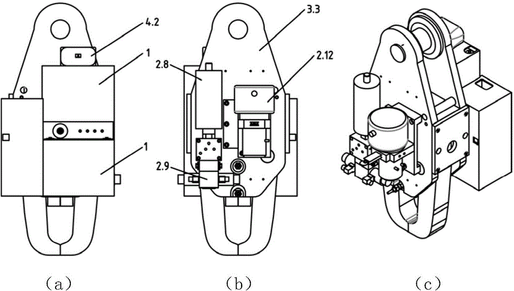
[0024] Such as Figure 1-4 As shown, an elevator counterweight frame clamping release device of the present invention includes a battery pack, a hydraulic power unit, a clamping release mechanism, and a remote control unit; the battery pack is connected to the hydraulic power unit, and the hydraulic power unit is connected to the clamping release mechanism; The battery pack is composed of two batteries 1 connected in series, the battery pack is fixed on the frame of the clamping release mechanism, the on-off of the battery pack is controlled by the remote control unit, and the remote control unit is composed of a remote control transmitter 4.1 and a remote control receiver 4.2 The remote control receiver 4.2 is installed on the frame of the clamping and releasing mechanism, and is connected with the battery pack;

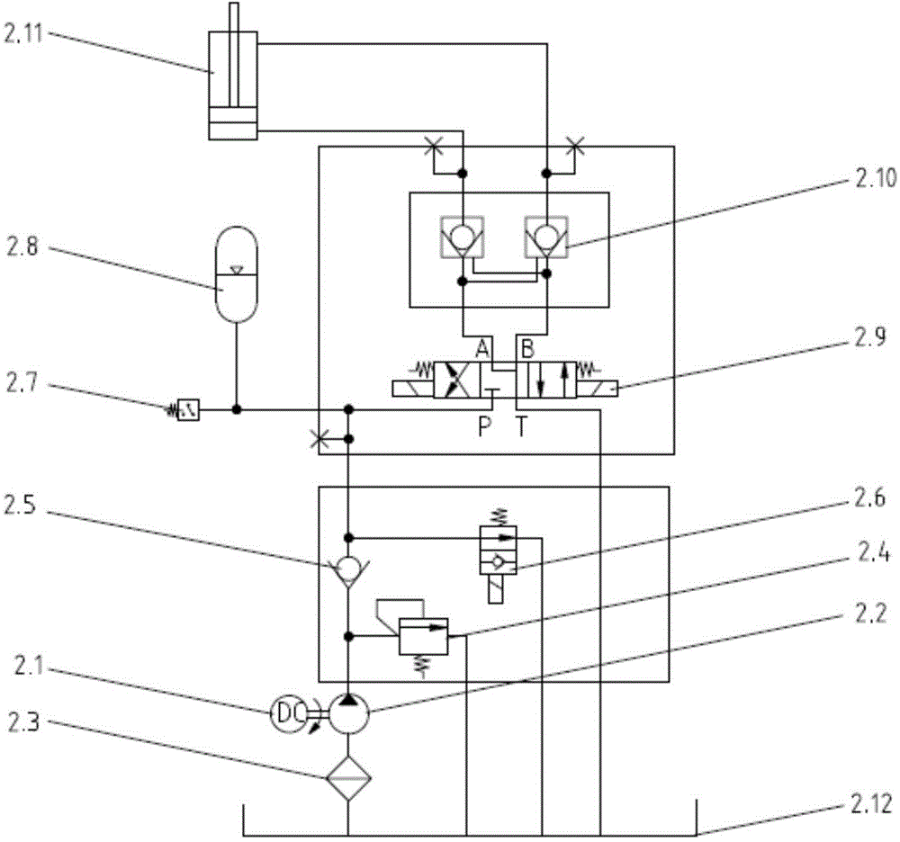
[0025] Such as figure 2 As shown, the hydraulic pow...


PUM


Abstract

The invention discloses an elevator counterweight frame clamping and releasing device. The elevator counterweight frame clamping and releasing device comprises a storage battery, a hydraulic power unit, a clamping and releasing mechanism and a remote operation unit. The hydraulic power unit comprises a direct-current motor, a gear pump, a filter, an overflow valve, a one-way valve, an unloading valve, a pressure relay, an energy accumulator, a magnetic exchange valve, a two-way hydraulic lock, a movement oil cylinder and an oil tank; the clamping and releasing mechanism comprises clamping arms, middle rods, a machine frame, machine frame and clamping arm connecting hinge pins, clamping arm and middle rod connecting hinge pins, middle rod and movement oil cylinder connecting hinge pins and movement oil cylinder piston rod guide sliding blocks; the remote operation unit comprises a remote control transmitter and a remote control receiver. The elevator counterweight frame clamping and releasing device can accomplish self-locking clamping and rapid release of an elevator counterweight frame in an elevator testing tower and meet diversified requirements for the release height of the counterweight frame, and has the advantages that remote operation and rapid release are achieved, the structure is compact, the functions are complete, and safety is high.

Description

technical field [0001] The invention relates to the field of elevator safety device testing, in particular to an elevator counterweight frame clamping and releasing device. Background technique [0002] With the increasing number of elevators produced and used in our country, the safety of elevators has been paid more and more attention. Elevator safety gear, buffers, safety protection circuits and other safety devices are key equipment for safe and reliable operation of elevators, and an important guarantee for the safety of elevator users' lives and property. At present, countries or industries have issued relevant test standards or methods for different elevator safety devices. The elevator safety device test must be carried out in the elevator test tower. For each test, the elevator counterweight frame is lifted to a different specified height and then released, so that the elevator counterweight frame moves freely to test the performance and reliability of the elevator...

Claims


Application Information

Patent Timeline
Patent Type & Authority Applications(China)
IPC IPC(8): F15B11/08F15B1/02G01M13/00
CPCB66B5/0093B25B11/00F15B1/02F15B21/08
Inventor 徐兵董朋鹏张军辉姚津津葛耀铮
Owner ZHEJIANG UNIV
Why Eureka
Try Eureka