
Efficient hydrotreating process for inferior heavy oil and residual oil

A technology for hydrogenation of residual oil and low-quality heavy oil, applied in the field of hydrogenation, can solve the problems of difficulty in obtaining products and benefits, high density of residual oil, and high viscosity, and achieve the effects of long device operation period, slowing down pressure drop, and simple operation.

Active Publication Date: 2014-01-29
PETROCHINA CO LTD
View PDF11 Cites 28 Cited by
  • Summary
  • Abstract
  • Description
  • Claims
  • Application Information

AI Technical Summary

Problems solved by technology

[0008] Residual oil has high density, high viscosity, and many impurities. It is difficult to obtain ideal products and benefits only by a single processing method.

Method used


Image

  • Efficient hydrotreating process for inferior heavy oil and residual oil
  • Efficient hydrotreating process for inferior heavy oil and residual oil
  • Efficient hydrotreating process for inferior heavy oil and residual oil

Examples


Embodiment 1

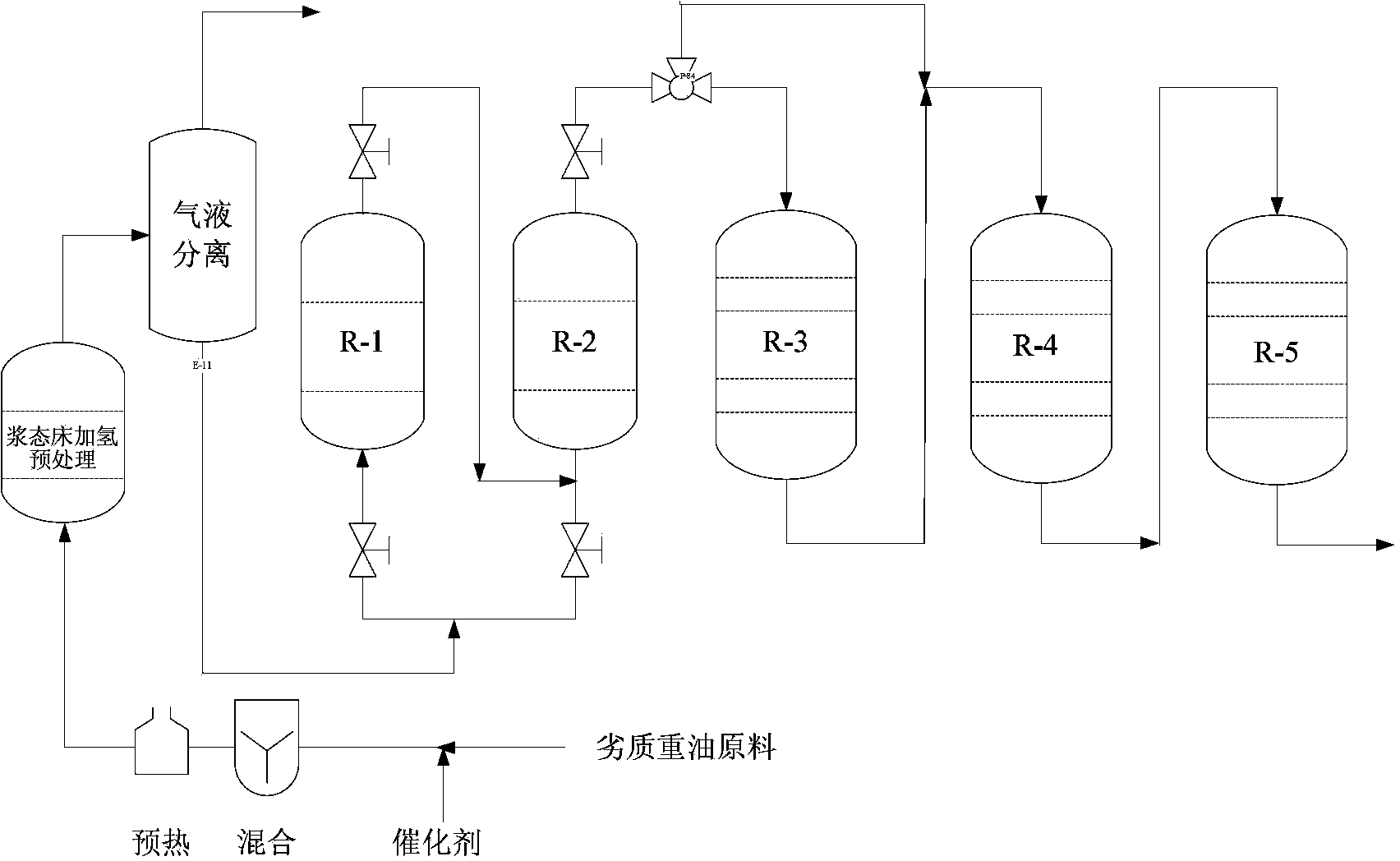
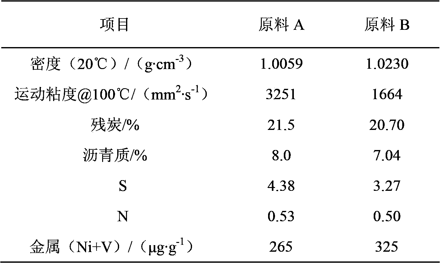
[0035] In this example, the inferior heavy oil hydrotreating process of the present invention is adopted, and raw material A is used as the raw material oil, and its properties are shown in Table 1. The slurry bed hydrogenation catalyst in the test process is prepared according to the method provided in CN101327439A embodiment 1, and the catalyst is non-supported Ni 2 P; The amount of catalyst added is 60 μg / g. The mixed raw materials and hydrogen enter the slurry bed hydrogenation reactor for reaction. After the reaction is completed, the product is separated from gas and liquid, and the liquid phase product enters the upflow type de-iron and decalcification reactors R-1 and R-2 of the hydrotreating unit, and The hydrodeferrification and decalcification catalyst is contacted to carry out the deferrification and decalcification reaction, and the reaction product directly enters the subsequent hydrotreating device without separation. The hydrodeferrification and decalcificatio...

Embodiment 2

[0038] In this example, the inferior heavy oil hydrotreating process of the present invention is adopted, and raw material B is used as the raw material oil, and its properties are shown in Table 1. The slurry bed hydrogenation catalyst in the test process is prepared according to the method provided in CN101327439A embodiment 2, and the catalyst is non-supported Ni 2 P; The amount of catalyst added is 250 μg / g. The mixed raw materials and hydrogen enter the slurry bed hydrogenation reactor for reaction. After the reaction is completed, the product is separated from gas and liquid, and the liquid phase product enters the upflow type de-iron and decalcification reactors R-1 and R-2 of the hydrotreating unit, and The hydrodeferrification and decalcification catalyst is contacted to carry out the deferrification and decalcification reaction, and the reaction product directly enters the subsequent hydrotreating device without separation. The hydrodeiron and decalcification cataly...


PUM


Abstract

The invention relates to an efficient hydrotreating process for inferior heavy oil and residual oil. The efficient hydrotreating process is characterized in that raw heavy oil or residual oil is mixed with a slurry-bed hydrogenation catalyst and then enters a slurry-bed hydrogenation reactor from the lower part together with hydrogen; after the reaction is done and the product is subjected to gas-liquid separation, a liquid product is subjected to slurry-bed hydro-upgrading, wherein reactors adopted in the slurry-bed hydro-upgrading mainly includes two up-flow type deferrization and decalcification reactors connected in series, a static bed demetalization reactor, a static bed desulphurization reactor and a static bed denitrification reactor which are put into service in sequence. By adopting the method, the capacity of the catalyst on removing impurities by hydrotreating is improved; the life cycle of the catalyst can be prolonged; the residual oil whuc is high in contents of metal, sulfur, nitrogen and asphalt can be treated; in addition, the pressure drop of the reactors can be effectively slowed down; therefore, the device can be operated for a long period.

Description

technical field [0001] The method of the present invention can be used in the field of hydrogenation, especially for high metal (Ni+V≥200μg·g -1 ), high carbon residue (CCR ≥ 20wt%), heavy distillate oil with high asphaltene content, residual oil and oil sand bitumen hydrofining and hydrotreating. The method of the invention not only has higher demetallization, desulfurization, denitrogenation and deasphaltene activities, but also has a longer device operation period. Background technique [0002] At present, with the worsening and heavier trend of crude oil, the increasing demand for light oil products and the increasingly stringent environmental protection regulations, the processing and upgrading technology of residual oil has attracted widespread attention from all over the world. The deep processing and upgrading of low-quality residual oil has important practical significance for rational utilization of petroleum resources, improvement of product quality, and increase...

Claims


Application Information

Patent Timeline
IPC IPC(8): C10G65/02
Inventor 周志远赵愉生赵元生刘元东张志国范建光陈芬芬崔瑞利梁迎春谭青峰程涛张春光胡长禄
Owner PETROCHINA CO LTD
Features
  • Generate Ideas
  • Intellectual Property
  • Life Sciences
  • Materials
  • Tech Scout
  • Unparalleled Data Quality
  • Higher Quality Content
  • 60% Fewer Hallucinations
Learn More