A long-term polarization probe for pipeline cathodic protection

A cathodic protection and polarization probe technology, applied in the field of pipeline systems, can solve the problems of contaminated electrodes, failure, semi-permeable membrane blockage, etc., to avoid leakage, reduce the volume of the cavity, and reduce the current demand.

Active Publication Date: 2015-08-12
PIPECHINA SOUTH CHINA CO
View PDF5 Cites 0 Cited by
  • Summary
  • Abstract
  • Description
  • Claims
  • Application Information

AI Technical Summary

Problems solved by technology

[0002] At present, most oil and gas pipeline cathodic protection polarization probes use microporous ceramic semi-permeable membranes for the conduction of the electrolyte inside and outside the reference electrode. Because the solvent is allowed to pass through under the action of osmosis for a period of time, it will inevitably lead to the leakage of the reference electrode solution or even Blockage of the semi-permeable membrane, contamination and oxidation of the electrode and eventually failure, although the use of a large-volume double-chamber structure and special fillers can alleviate this problem and prolong the service life of the polarization probe, but it cannot fundamentally solve this problem
In addition, the polarized test piece of most polarized probes is located on the lower surface of the probe, and it is impossible to ensure that the entire area of ​​the polarized test piece is in close contact with the soil after backfilling
[0003] CN201319014Y discloses a polarization test probe, "Gas and Heat" Volume 30, Issue 4 discloses an "Application of Polarization Probes in Cathodic Protection of Buried Steel Pipelines", and CN2915885Y discloses a buried type copper / copper sulphate reference electrode, but none of them have ideal lifetime

Method used


Image

  • A long-term polarization probe for pipeline cathodic protection
  • A long-term polarization probe for pipeline cathodic protection
  • A long-term polarization probe for pipeline cathodic protection

Examples


Embodiment Construction

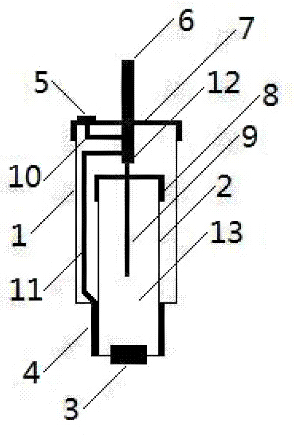
[0028] Embodiment. The specific embodiment of the present invention is described with this example and the present invention is described further. This example is an experimental prototype, its composition is as follows figure 1 shown.

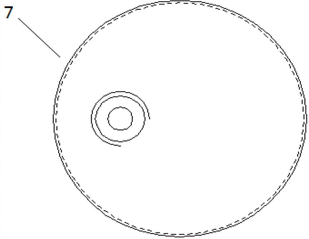
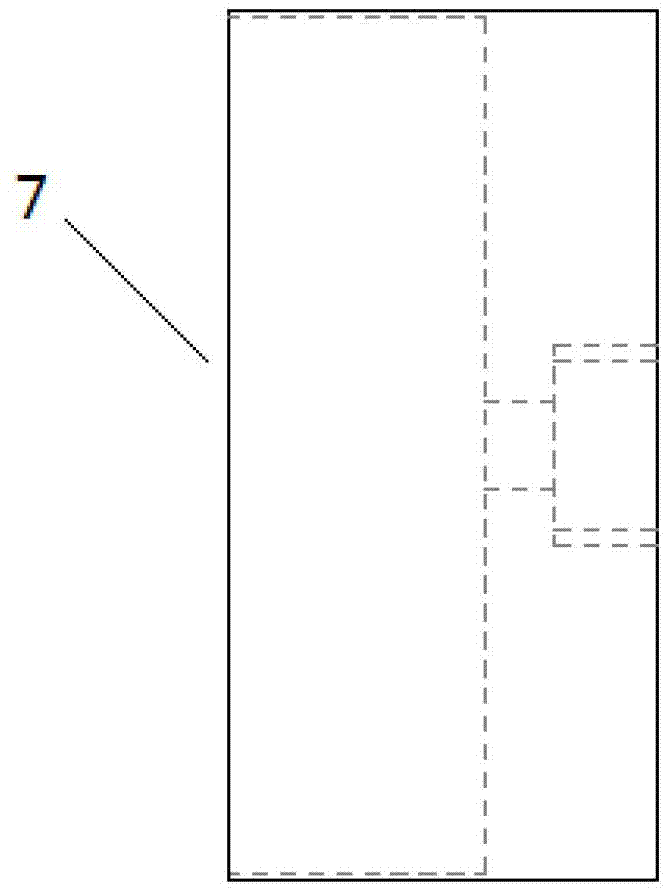
[0029] This example consists of outer cavity 1, inner cavity 2, ion-conducting polymer 3, polarization test piece 4, self-corrosion test piece 5, cable 6, outer cover 7, inner cover 8, copper rod 9, lead wire I10, lead wire II11, Composition of lead wire III12 and saturated copper sulfate solution 13. The inner cavity 2 is set in the middle and lower part of the outer cavity 1 and extends out of the outer cavity 1, and the ion-conductive polymer 3 is fixed at the bottom center of the inner cavity 2; the inner cavity 2 has an inner cover 8, and the outer cavity 1 has an outer cover 7; The self-corrosion test piece 5 is fixed on the outside of the outer cover 7, and the outer cover 7 is sealed with the outer cavity 1 through threads and gaske...


PUM


Abstract

The invention provides a long-acting polarization probe with pipeline cathodic protection. The long-acting polarization probe is characterized in that an inner cavity (2) is sleeved at the inner lower middle part of an outer cavity (1) and extends out of the outer cavity (1); an ion-conductive polymer (3) is fixed in the center of the bottom of the inner cavity (2); an inner cover (8) is arranged on the inner cavity (2), and an outer cover (7) is arranged on the outer cavity (1); a self-corrosion test block (5) is fixed outside the outer cover (7), and the outer cover (7) is in fit sealing with the outer cover (1) through threads and a gasket; a polarization test block (4) and the inner cover (8) are in fit sealing with the inner cavity (2); a copper bar (9) is inserted into the inner cavity (2) from the top and sealed on the inner cover (8); a cable (6) enters the upper part of the outer cavity (1) through the outer cover (7); saturated copper-bath (13) is filled in the inner cavity (2). By adopting the long-acting polarization probe with the pipeline cathodic protection, the permeation and dropping of a reference electrode solution can be avoided, the blocking of a semipermeable membrane can be avoided, and an electrode can be prevented from corrosion; the service life of the long-acting polarization probe is long; the polarization test block can be tightly contacted with the soil.

Description

technical field [0001] The invention is a long-term polarization probe for pipeline cathodic protection. It relates to the technical field of piping systems. Background technique [0002] At present, most oil and gas pipeline cathodic protection polarization probes use microporous ceramic semi-permeable membranes for the conduction of the electrolyte inside and outside the reference electrode. Because the solvent is allowed to pass through under the action of osmosis for a period of time, it will inevitably lead to the leakage of the reference electrode solution or even The clogging of the semi-permeable membrane, the contamination and the oxidation of the electrode eventually lead to failure. Although the use of a large-volume double-chamber structure and special fillers can alleviate this problem and prolong the service life of the polarization probe, it cannot fundamentally solve this problem. In addition, the polarized test piece of most polarized probes is located on t...

Claims


Application Information

Patent Timeline
Patent Type & Authority Patents(China)
IPC IPC(8): C23F13/22G01N27/31
Inventor 张丰王维斌薛致远毕武喜赵君刘玲莉熊金根安龙虎
Owner PIPECHINA SOUTH CHINA CO
Why Eureka
Try Eureka