Wireless communication power relay system

A power relay and wireless communication technology, applied in signal transmission system, general control system, transmission system, etc., can solve problems such as remote control, and achieve the effect of simple interface design and high-level protocol, long transmission distance and low cost

Inactive Publication Date: 2014-01-29
TAIZHOU FUCCESSO ELECTRONICS TECH
View PDF0 Cites 0 Cited by
  • Summary
  • Abstract
  • Description
  • Claims
  • Application Information

AI Technical Summary

Problems solved by technology

[0004] The technical problem to be solved by the present invention is to provide a wireless communication power relay system and its use method, which solves the problem of remote control of power relays in places where it is inconvenient for some personnel to enter, or when power relays are remotely distributed in multiple places. question

Method used


Image

  • Wireless communication power relay system
  • Wireless communication power relay system
  • Wireless communication power relay system

Examples


Embodiment

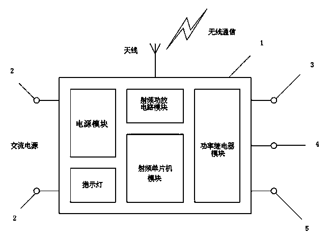
[0030] Embodiment A wireless communication power relay system

[0031] Such as figure 1 , the wireless communication power relay system of this embodiment adopts such as figure 1 The structure shown includes: shell 1, power input terminal 2, relay output terminal (including common terminal pin 3, normally open terminal pin 4, normally closed terminal pin 5), indicator light, RF microcontroller module, power supply modules and power relay modules. Among them, the case size of the power relay system for wireless communication is 82*50*32MM. The power input terminal is a 2 PIN green phoenix terminal, which is placed on the left side of the outer shell and is used to connect to an 85~265 V AC power supply. The relay output terminal is a 3 PIN green phoenix terminal, which is placed on the right side outside the shell and used to connect the load. The maximum AC voltage of the load is 277V AC, the maximum DC voltage is 30V, and the maximum current is 10A. The signal indicato...


PUM


Abstract

The invention discloses a wireless communication power relay system. The system is characterized by comprising a shell, a power input terminal, a relay output terminal, an indicator light, a radio frequency single-chip microcomputer module, a power module, a power relay module, and a remote control center. The power input terminal is used for being connected with an alternating current power supply. A common terminal pin, a normally open terminal pin and a normally closed terminal pin of the relay output terminal are used for being connected with loads. The system has the advantages that on or off of the power relay is controlled through wireless packets monitored and the current state of the power relay is fed back to the remote control center in a wireless manner.

Description

technical field [0001] The invention belongs to the technical field of industrial automation control and wireless communication, and in particular relates to a device for automatically controlling a power relay by using wireless communication technology and a method for using the same. Background technique [0002] Relay is an electronic control device, it has a control system (also known as input circuit) and a controlled system (also known as output circuit), usually used in automatic control circuits, it actually uses a smaller current to control a larger An "automatic switch" of electric current. Therefore, it plays the role of automatic adjustment, safety protection, and conversion circuit in the circuit. [0003] The traditional power relay control adopts the wired control method. However, in some places where it is inconvenient for personnel to enter, or when the relays are remotely distributed in multiple places, the wired control method is not suitable. Contents ...

Claims


Application Information

Patent Timeline
Patent Type & Authority Applications(China)
IPC IPC(8): G05B19/042H04L29/08G08C17/02
Inventor 王锋
Owner TAIZHOU FUCCESSO ELECTRONICS TECH
Why Eureka
Try Eureka