Sensor component for an optical flow rate sensor

A flow sensor and sensor technology, applied in scientific instruments, material analysis through optical means, instruments, etc., to save processing time and meet optical requirements

Active Publication Date: 2014-01-29
SCHOTT AG
View PDF13 Cites 3 Cited by
  • Summary
  • Abstract
  • Description
  • Claims
  • Application Information

AI Technical Summary

Problems solved by technology

This has the disadvantage that, as previously described, only one component of the medium, e.g. ethanol, can be determined

Method used


Image

  • Sensor component for an optical flow rate sensor
  • Sensor component for an optical flow rate sensor
  • Sensor component for an optical flow rate sensor

Examples


Embodiment Construction

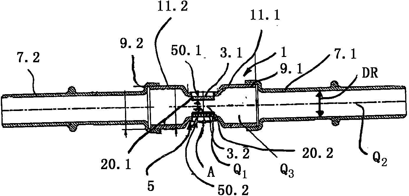
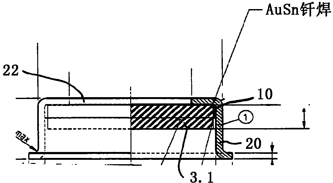
[0066] figure 1 The sensor component 1 according to the invention is shown in a schematic view with two sight glasses 3 . 2 , 3 . 1 installed in the region of the sensor section 5 for the sensor component of the optical flow sensor 4 . The sight glass 3.2, 3.1 currently utilizes metal solder or glass solder with the containment member (which is referred to here as in image 3 Covers 20 , 20 . 1 , 20 . 2 as specifically described in ) are connected and fitted into each recess 50 . 1 , 50 . 2 of the sensor component and are materially interlocked with the sensor component 1 , for example by soldering or laser welding. connect. The sensor component 1 and thus the optical flow sensor is again mounted or coupled to the pipe with the pipe pieces 7.1, 7.2. The connection of the pipes 7 . 1 , 7 . 2 to the sensor components of the optical flow sensor 1 takes place in the regions 9 . 1 , 9 . 2 of the sensor components 1 . The sensor component 1 of the optical flow sensor comprises, i...


PUM


Abstract

The invention relates to a sensor component for an optical flow rate sensor for fluid and / or gaseous media, comprising at least one component segment and at least one sensor segment, the sensor segment comprising at least two inspection windows in the region of a plurality of cutouts in a sensor segment disposed such that it is possible for light to pass through a transverse section of the sensor segment, or the sensor segment comprising exactly one inspection window in the region of a cutout and a reflective surface, in particular a mirrored or polished surface, being provided on the side opposite the cutout, such that it is possible for light to pass through the sensor segment twice through a transverse section of the sensor segment, characterized in that the sensor component comprises a receiving component that can be inserted in the one or more cutouts and the sight glass is bonded to the receiving component.

Description

technical field [0001] The invention relates to a sensor component of an optical flow sensor, in particular for fluid and / or gaseous media, comprising at least one component section and at least one sensor section, wherein the sensor section comprises at least one or more recesses, At least one viewing glass is arranged in the gap. Background technique [0002] A sensor component in the form of a flow sensor is known from DE 10 2008 058 071 A1, in which the physical properties of a medium (eg liquid or gas) are determined. The medium whose physical properties (eg temperature) are detected is, for example, guided in a piping system or stored in a container (eg a tank). The sensors described in DE 10 2008 058 071 A1 include only mechanical and electrical sensors, such as humidity sensors, pressure sensors, capacitive sensors, sensors for measuring electrical conductivity and temperature sensors. Optical sensors have so far not been used for determining physical properties in...

Claims


Application Information

Patent Timeline
Patent Type & Authority Applications(China)
IPC IPC(8): G01N21/03
CPCG01N21/0303Y10T29/49826G01N21/61
Inventor 莱茵哈德·兰夫特尔赫尔穆特·哈特尔
Owner SCHOTT AG
Why Eureka
Try Eureka