Fuel supply system and construction machine
A technology of civil engineering and oil supply system, applied in control/adjustment system, manufacturing tool, bending workpiece, etc., can solve the problems of fuel supply, large production loss, etc., and achieve the effect of suppressing the reduction of productivity
- Summary
- Abstract
- Description
- Claims
- Application Information
AI Technical Summary
Problems solved by technology
Method used
Image

Examples
Embodiment 1
[0042] The fuel supply system of Example 1 was assembled into a cargo transportation system. The cargo transport system is a system for transporting cargo carried by civil engineering machinery. A construction machine or a mining machine is used as a civil engineering machine, and in Embodiment 1, a transportation machine such as a dump truck as a mining machine will be described.
[0043]
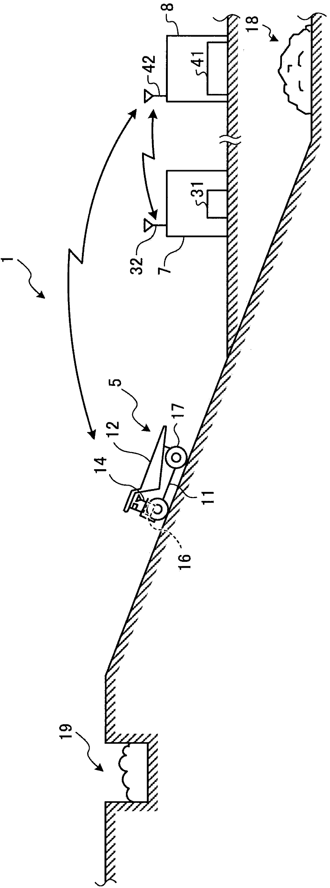
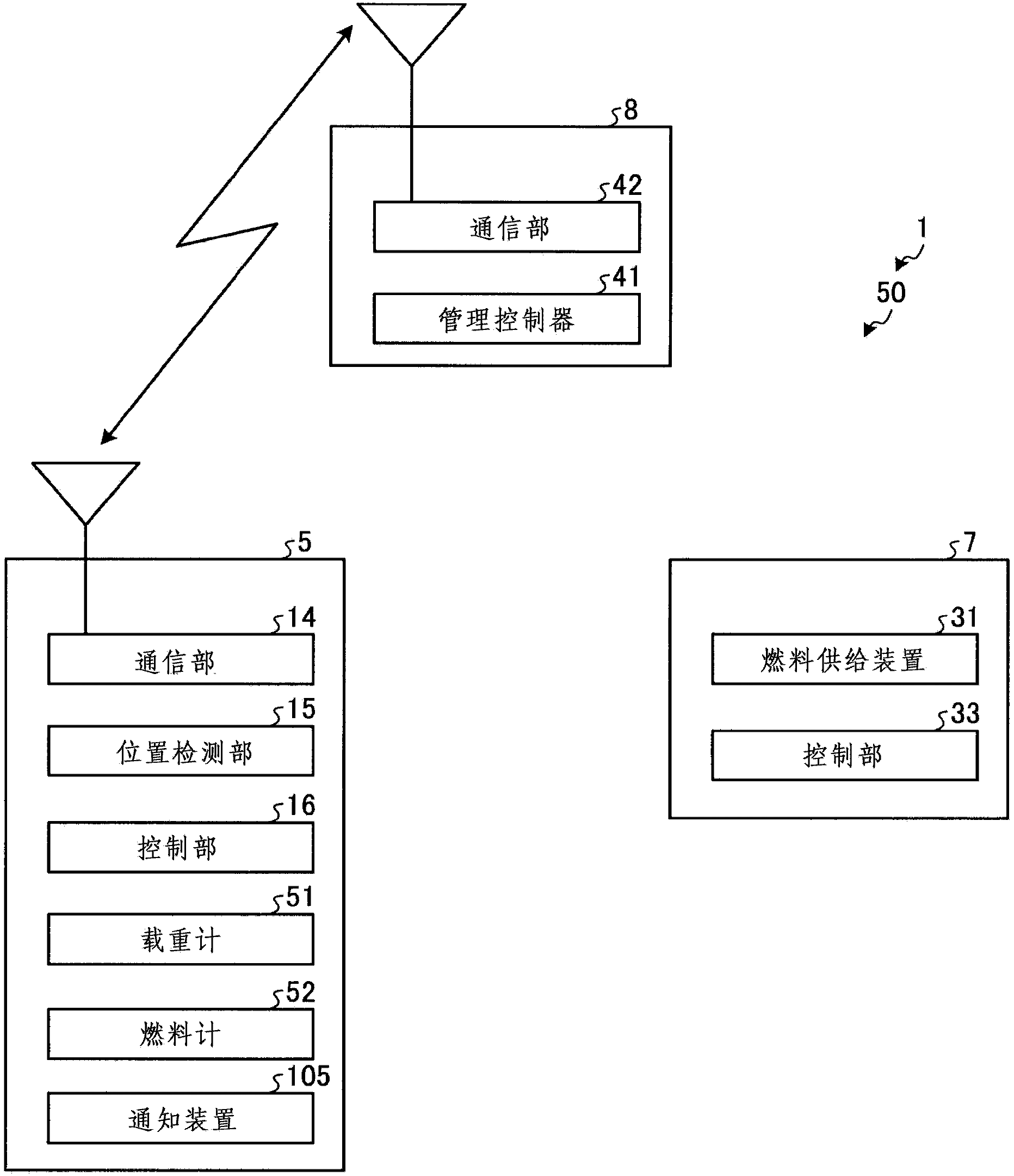
[0044] figure 1 It is a schematic diagram showing the outline of a cargo transportation system using the fuel supply system of Example 1. Such as figure 1 As shown, the cargo transportation system 1 is used in mines and the like, and has transportation machinery 5, oil supply equipment 7, and central management control equipment 8 for managing and controlling them.
[0045] The transportation machine 5 is, for example, a dump truck, and can be loaded with cargo and run. This transportation machine 5 has a vehicle main body 11, a cargo bed 12, a communication unit 14, and a position det...
Embodiment 2
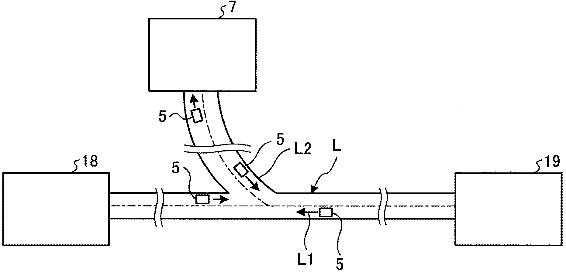
[0073] Next, refer to Figure 5 as well as Figure 6 The fuel supply system 110 of the second embodiment will be described. Figure 5 It is an explanatory diagram of the traveling route of the transportation machine of the second embodiment, Figure 6 It is a block diagram showing the configuration of the fuel supply system of the second embodiment. In addition, in the fuel refueling system 110 of the second embodiment, in order to avoid redundant description, only the parts different from the fuel refueling system 50 of the first embodiment will be described. While the notifying device 105 is provided as a display monitor in the cab of the transportation machine 5 in the fuel supply system 50 of Embodiment 1, the notification device 115 is provided outside the transportation machine 5 in the fuel supply system 110 of Embodiment 2.
[0074]
[0075] Such as Figure 5 As shown, the notification device 115 is an alarm device such as a signal machine or an electro-optical d...
Embodiment 3
[0083] Next, refer to Figure 7 as well as Figure 8 The fuel supply system 120 of the third embodiment will be described. Figure 7 It is an explanatory diagram of the traveling route of the transportation machine of the third embodiment, Figure 8 It is a block diagram showing the configuration of the fuel supply system of the third embodiment. In addition, also in the fuel refueling system 120 of the third embodiment, only the parts different from the fuel refueling system 110 of the second embodiment will be described in order to avoid redundant description. While the notification device 115 is provided outside the transportation machine 5 in the fuel supply system 110 of Embodiment 2, in the fuel supply system 120 of Embodiment 3, an access control device 125 is provided instead of the notification device 115 .
[0084]
[0085] Such as Figure 7As shown, the access control device 125 is installed on the travel path L2 and is configured to restrict the transportatio...
PUM
 Abstract
Description
Claims
Application Information
 - R&D
- Intellectual Property
- Life Sciences
- Materials
- Tech Scout
- Unparalleled Data Quality
- Higher Quality Content
- 60% Fewer Hallucinations
Browse by: Latest US Patents, China's latest patents, Technical Efficacy Thesaurus, Application Domain, Technology Topic, Popular Technical Reports.
© 2025 PatSnap. All rights reserved.Legal|Privacy policy|Modern Slavery Act Transparency Statement|Sitemap|About US| Contact US: help@patsnap.com