Method for monitoring storage cell, system for monitoring storage cell, and storage cell system

A battery system and monitoring system technology, applied in the direction of secondary battery charging/discharging, battery circuit devices, secondary batteries, etc., can solve problems such as battery degradation

Active Publication Date: 2014-01-29
PANASONIC INTELLECTUAL PROPERTY MANAGEMENT CO LTD
View PDF9 Cites 13 Cited by
  • Summary
  • Abstract
  • Description
  • Claims
  • Application Information

AI Technical Summary

Problems solved by technology

[0008] However, even if the deterioration state of the battery is correctly diagnosed, the actual progress of the deterioration of the battery varies depending on the current state of deterioration of the battery, operating environment, or operating conditions.
Therefore, if the charging and discharging of the storage battery are controlled regardless of the deterioration state of the storage battery, the deterioration of the storage battery will progress.

Method used


Image

  • Method for monitoring storage cell, system for monitoring storage cell, and storage cell system
  • Method for monitoring storage cell, system for monitoring storage cell, and storage cell system
  • Method for monitoring storage cell, system for monitoring storage cell, and storage cell system

Examples


Embodiment approach 1

[0052] [1. Composition]

[0053] (1.1 System composition diagram)

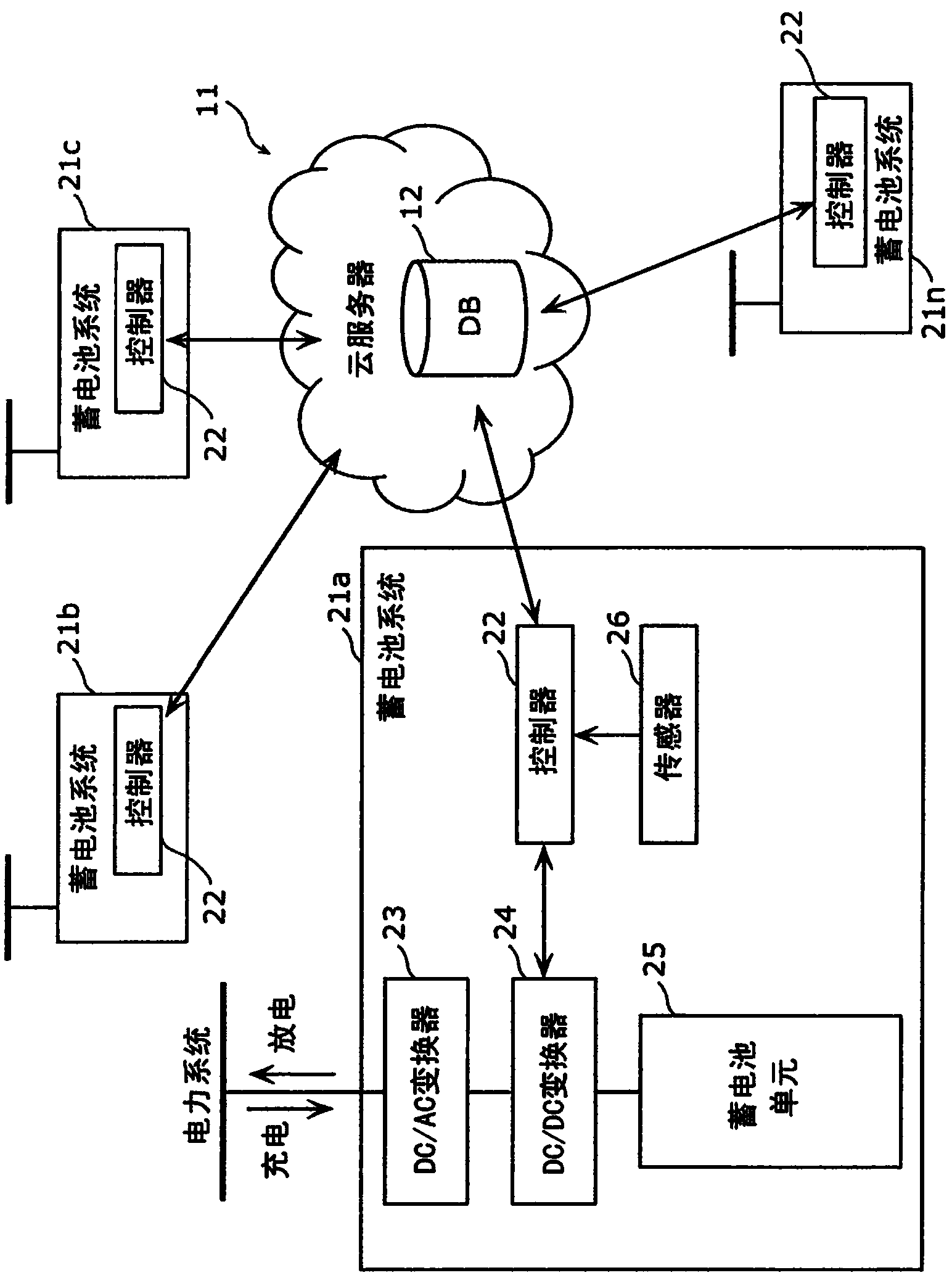
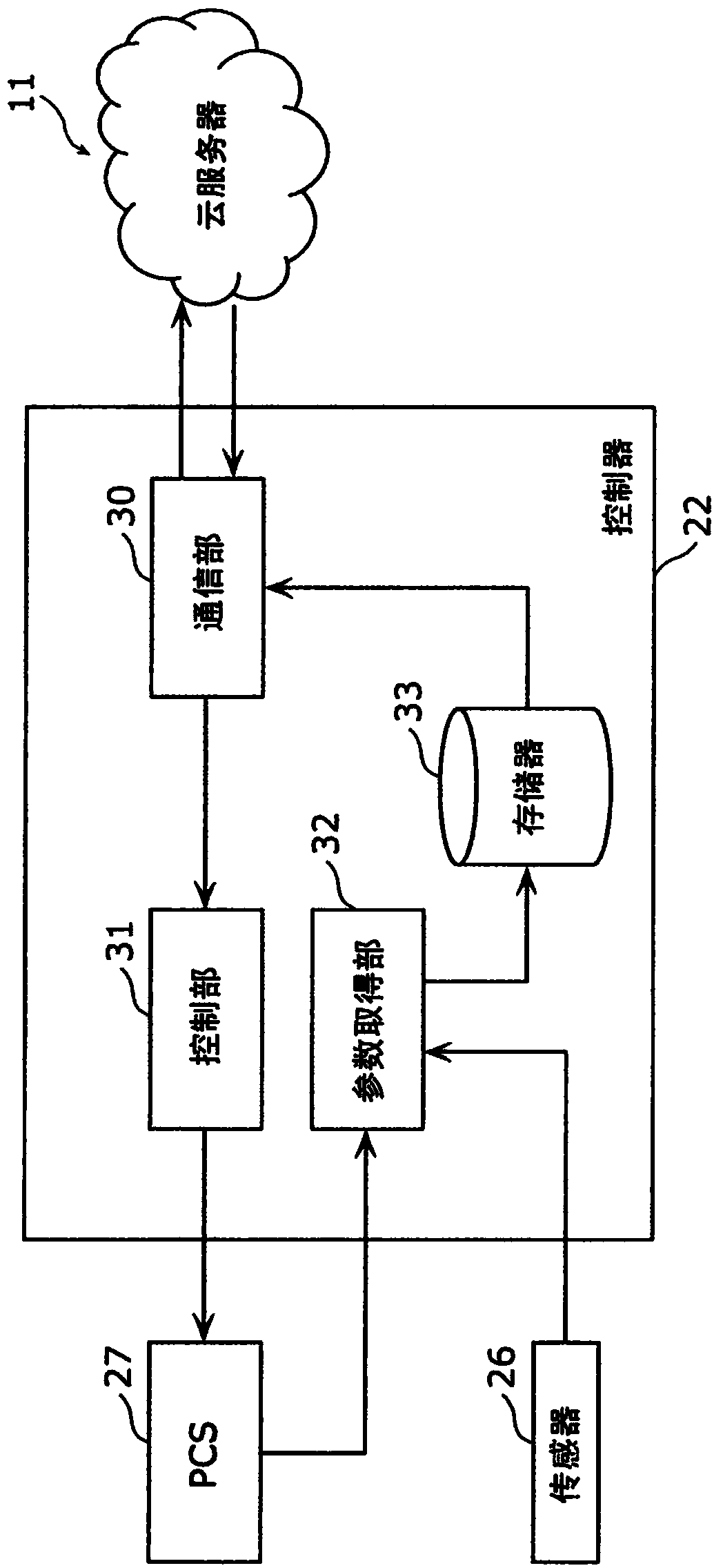
[0054] figure 1 This is an example of the system configuration of the storage battery monitoring system according to the first embodiment. figure 1 Among them, the cloud server 11 is connected to a plurality of storage battery systems 21 a , 21 b , 21 c , .

[0055] The battery system 21 includes, for example, a controller 22 , a DC / AC converter 23 (also sometimes referred to as an “inverter”), a DC / DC converter 24 , a battery unit 25 , and a sensor 26 .

[0056] Hereinafter, the DC / AC converter 23 and the DC / DC converter 24 may be collectively referred to as a power conditioning system, or the DC / AC converter 23 may be referred to as a power conditioning system (hereinafter, abbreviated as “PCS 27 ”).

[0057] figure 1 In the above, the case where one battery unit 25 is provided in the battery system 21 is described as an example, but the embodiment of the battery unit 25 is not limited to this case. Tha...

Embodiment approach 2

[0175] In Embodiment 2, such as Figure 13 As shown, the remote control system of the storage battery in the case where the cloud server 11 is connected to the system operator 60 will be described.

[0176] The cloud server 11 according to Embodiment 1 remotely controls charging and discharging of each storage battery system 21 according to the deterioration state of each storage battery system 21 . In Embodiment 2, when the cloud server 11 receives a control command value for controlling the voltage or frequency of the electric power system from the system operator, it determines whether each storage battery system 21 should 21 The amount of electricity charged or discharged.

[0177] Furthermore, upon receiving the control command value from the system operator 60 , the cloud server 11 may determine the storage battery system 21 used for voltage control or frequency control of the power system based on the efficiency of the DC / AC converter 23 . In this case, the cloud serv...


PUM


Abstract

A method for monitoring a storing cell, wherein the method comprises: receiving identification information indicative of a storage cell system and property data indicative of the state of one or more storage cells via a communication network; determining a degradation model corresponding to the one or more storage cells by using degradation models indicative of degradation trends of other storage cells managed in a database, on the basis of the received property data; and, over the communication network, generating control data for improving the degradation state of the one or more storage cells at a predetermined time in accordance with the corresponding degradation model and sending the generated control data to the storage cell system; the one or more storage cells being controlled in the storage cell system on the basis of the sent control data.

Description

technical field [0001] The present invention relates to a storage battery monitoring method, a storage battery monitoring system, and a storage battery system for managing characteristics of a storage battery and remotely controlling the storage battery. Background technique [0002] Conventionally, techniques for estimating the deterioration state or abnormal state of the storage battery have been studied. For example, in the information management system described in Patent Document 1, the server manages life information of storage batteries that have reached the end of their life. When the server determines that the storage battery has reached the end of its life, the server associates the current use environment of the storage battery with the use state information and stores it as life information. [0003] prior art literature [0004] patent documents [0005] Patent Document 1: Japanese Patent Laid-Open No. 2011-69693 [0006] Summary of the invention [0007] T...

Claims


Application Information

Patent Timeline
Patent Type & Authority Applications(China)
IPC IPC(8): H01M10/42H01M10/44H01M10/48H02J7/10H02J13/00
CPCY02E60/12G06F1/28H02J13/00H01M2010/4278H01M10/48H04Q2209/10H04Q2209/40H04Q9/00G01R31/367G01R31/392Y02E60/10Y02E60/00H02J7/04H02J13/00022H02J13/00002Y04S10/30H02J7/007192
Inventor 花房宽
Owner PANASONIC INTELLECTUAL PROPERTY MANAGEMENT CO LTD
Why Eureka
Try Eureka