Self-supporting housing of a dynamo-electric machine

An electric motor, self-supporting technology, applied in the direction of electric components, casings/covers/supports, electrical components, etc., can solve the problem of large effective parts, etc., and achieve simple methods and methods, optimized material application, and high rigidity Effect

Active Publication Date: 2014-01-29
SIEMENS AG
View PDF10 Cites 3 Cited by
  • Summary
  • Abstract
  • Description
  • Claims
  • Application Information

AI Technical Summary

Problems solved by technology

[0004] Electric motors with a housing result in a larger active part, that is, in other words the cooling range provided is not the same as for machines without a housing

Method used


Image

  • Self-supporting housing of a dynamo-electric machine
  • Self-supporting housing of a dynamo-electric machine
  • Self-supporting housing of a dynamo-electric machine

Examples


Embodiment Construction

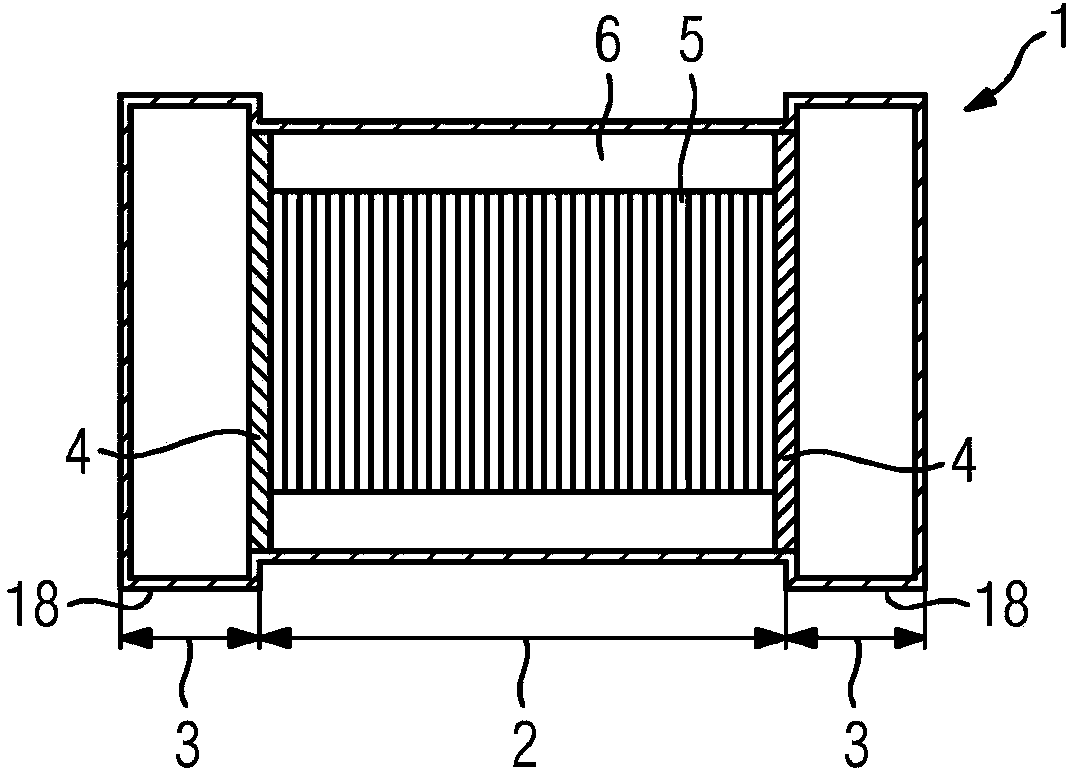
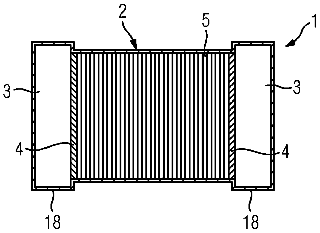
[0053] figure 1 Shows a principled longitudinal sectional view of a self-supporting housing 1 according to the invention of an electric motor 23 with a stator 22 whose plate pack 5 is layered by the shaft via a pressure plate 4 on the end face Laminated composition. With regard to the type of construction of the self-supporting shell 1 , shell parts or shell sections, reinforcements, profiles and cladding are connected to one another using different joining techniques (soldering, welding, gluing). In this case, the load-bearing function is assumed solely by this housing structure. Rigidity is achieved by a compact housing construction, by possibly hollow housing parts with as large a cross-section as possible, and thus by a high resistance moment. For example, in Figure 8 and Figure 23 Beads, recesses (Eindellung), etc. in the center increase rigidity.

[0054] In particular, the housing 1 must be able to absorb the moments that occur during operation, so that it also s...


PUM


Abstract

The invention relates to a self-supporting housing (1) of a laminated core (5) of a stator (22) in a dynamo-electric machine (23), said housing (1) having the following features: a laminated core section (2) surrounding the laminated core (5) which is formed by axially stacked sheets and includes at least one pressure plate (4) on its faces, the inside of the laminated core section (2) being designed such that a laminated core (5) having a basic shape of an octagonal cross-section can be accommodated in the laminated core section, wherein shorter sides (25) and longer sides (24) of the laminated core alternate in the peripheral direction; at least one connecting section (3) in the axial extension of the laminated core section (2) in order to dispose additional elements and / or devices on the housing (1); contact zones (7) on the inside of the laminated core section (2) in order to dispose and secure the laminated core (5) in such a way that a gap (6) is formed between the contact zones (7).

Description

technical field [0001] The present invention relates to a self-supporting housing for a plate pack of a stator of an electric motor, for positioning a stator in a self-supporting housing a plate pack of a self-supporting housing, and with a A stack of plates in the stator of an electric motor. Background technique [0002] There are many motor designs, not only for gas cooling and water cooling, for terminal box mounting, for bearing arrangements, but also for specific designs for cooling electric motors. A gas cooling solution is known from EP 0 387 743 A1 for this purpose. DE 197 42 255 C1 describes a housingless three-phase AC motor with axis-parallel cooling ducts in the stator stack. Furthermore, liquid-cooled electric motors are known from US Pat. No. 5,084,642 A and DE 9,112,631 U1, wherein in this case the steering and the input and output are inserted into the end shields. Here, every change in shaft height, type of cooling, arrangement of the terminal box leads ...

Claims


Application Information

Patent Timeline
Patent Type & Authority Applications(China)
IPC IPC(8): H02K1/18H02K1/20H02K5/24
CPCH02K9/10H02K1/20H02K9/04H02K1/185H02K5/24H02K5/207H02K5/203
Inventor 赖纳·格里勒恩贝格尔托马斯·科克乌尔里希·维尔纳马丁·辛德尔卡格哈德·多尔
Owner SIEMENS AG
Why Eureka
Try Eureka