Artificial dental implant, artificial dental implanting system and implanting method

A technology for implants and artificial teeth, which is applied in the fields of implants, dentistry, and dental restorations, etc. It can solve problems such as the inability to discharge or accommodate bone chips, loosening of implants and abutments, and failure of artificial tooth implants, etc., to achieve immediate loading , Avoid the effect of difficult cutting and not easy to get stuck

Inactive Publication Date: 2014-02-05
DALIAN SANSHENG SCI & TECH DEV
View PDF16 Cites 14 Cited by
  • Summary
  • Abstract
  • Description
  • Claims
  • Application Information

AI Technical Summary

Problems solved by technology

[0005] The purpose of the present invention is to solve the difficulty in cutting and bone burns caused by excessive cutting force during planting of the above-mentioned existing implants; , resulting in the problem of low lifespan of implants, an artificial dental implant (implant for short) is proposed

Method used


Image

  • Artificial dental implant, artificial dental implanting system and implanting method
  • Artificial dental implant, artificial dental implanting system and implanting method
  • Artificial dental implant, artificial dental implanting system and implanting method

Examples


Embodiment 1

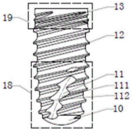
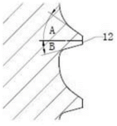
[0050] figure 1 It is the front view of the artificial dental implant of the present invention; figure 2 It is a perspective view of the artificial dental implant of the present invention; image 3 for figure 1 Enlarged view of medium and fine threads; Figure 4 for figure 1 Enlarged view of a medium-coarse thread; Figure 5 for figure 1 bottom view of Figure 6 for figure 1 top view.

[0051] The artificial tooth implant disclosed in this embodiment is made of pure titanium, such as figure 1 As shown, the outer surface of the implant is provided with threads, the two ends of the implant are respectively a neck 19 and a head 18, and the outer surface of the head 18 is provided with a helical self-tapping groove 11, and the helical direction of the helical self-tapping groove 11 is The helical direction of the thread is right-handed, and the thread lead angle of the helical self-tapping groove 11 is greater than the thread lead angle of the thread. The self-tapping g...

Embodiment 2

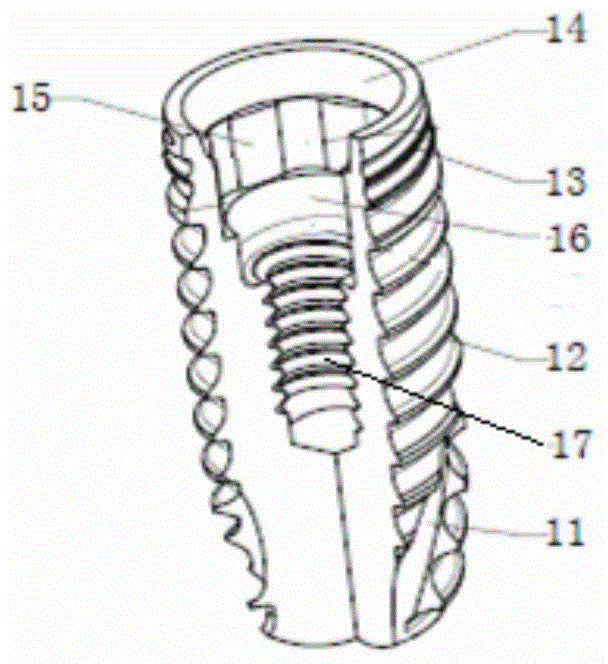
[0058] Figure 7 It is a three-dimensional exploded view of the artificial tooth implant system of the present invention; Figure 8 It is a structural schematic diagram of the abutment of the present invention; Figure 9 It is a structural schematic diagram of the central bolt of the present invention; Figure 10 It is a schematic diagram of the structure of the artificial tooth implant system in the oral cavity of the present invention.

[0059] This embodiment discloses a kind of artificial tooth implant system, such as Figure 7 As shown, it includes the artificial dental implant 1 described in Embodiment 1, the abutment 2 and the central bolt 3 .

[0060] Such as Figure 8 As shown, the two ends of the abutment 2 are respectively the crown connection section 29 and the implant connection section, and the middle of the crown connection section 29 and the implant connection section is the gingival section. The crown connection section 29 is a conical frustum with two tape...


PUM


Abstract

The invention provides an artificial dental implant, an artificial dental implanting system and an implanting method. A screwed thread is formed in the outer surface of an artificial dental implant, wherein a neck part and a head part are respectively arranged at two ends of the implant; a spiral tapping slot is formed in the outer surface of the head part, the spiral direction of the spiral tapping slot is the same as that of the screwed thread, and the spiral lead angle of the spiral tapping slot is different from that of the screwed thread. When the artificial dental implant is implanted, the cutting force and extrusion force of the implant to the bone tissues at the implanted position are reasonable, and the bone is effectively protected from injury; the artificial dental implant can accommodate bone chips generated in the tapping process, and the bone healing time can be shortened; the artificial dental implant is effectively prevented from rotating or loosing, and the service life of artificial tooth can be prolonged.

Description

technical field [0001] The invention relates to the technical field of oral medical devices, in particular to an artificial tooth implant, an artificial tooth implant system and an implant method. Background technique [0002] With the continuous development of oral implant technology, the "artificial implant" technology has gradually matured and stabilized. Artificial dental implants are to first place a highly biocompatible titanium artificial tooth root into the alveolar for fixation and suture, and after several months to wait for the artificial tooth root to be firmly connected to the bone in the alveolar, the follow-up denture installation is carried out. The artificial tooth root of "artificial implant" is directly combined with the bone, which can provide better supporting force and can chew hard food, so it is very popular. The stability of the implant (root) in the early stage of the artificial dental implant process and the firmness of the connection between the ...

Claims


Application Information

Patent Timeline
Patent Type & Authority Applications(China)
IPC IPC(8): A61C8/00
Inventor 张久文张保荣李闪彭鹏蒋志
Owner DALIAN SANSHENG SCI & TECH DEV
Why Eureka
Try Eureka