Controlled rolling and controlled cooling system for bars

A technology of controlled rolling, controlled cooling, and rods, which is applied in metal rolling, temperature control, metal rolling, etc., can solve the problems of insufficient cooling capacity of the cooling bed, low pass rate, unevenness, etc., and achieve a solution to the cooling capacity of the cooling bed Insufficient, strong application adaptability, and the effect of reducing the cooling range

Active Publication Date: 2014-02-05
CENT RES INST OF BUILDING & CONSTR CO LTD MCC GRP +1
View PDF6 Cites 35 Cited by
  • Summary
  • Abstract
  • Description
  • Claims
  • Application Information

AI Technical Summary

Problems solved by technology

[0002] At present, the structure and layout of the cooler or the water penetrator of the existing bar controlled rolling and controlled cooling system are very backward, and there are two main problems: on the one hand, although it can cool the bar, the cooling effect is not ideal, and it is directly Affect the microstructure and performance of the bar, for example, the metallographic structure of the bar is not ideal, the grains are coarse and uneven, which makes it difficult to improve the performance of the finished bar, especially the qualified rate of the finished bar with high quality requirements is low, often need to add A large number of alloys are used to make up for it, which also leads to the high cost of producing steel bars above grade 3, and the cooling capacity of the cooling bed is insufficient after the output of the rolling mill is increased; on the other hand, the application adaptability is poor, and it is often limited to certain steel types and / or certain When the steel grade and / or the bar specification are changed, the bar controlled rolling and cooling system is often not suitable for the new production conditions, and it is necessary to re-lay the cooler and the corresponding pipeline, which is time-consuming and laborious

Method used


Image

  • Controlled rolling and controlled cooling system for bars
  • Controlled rolling and controlled cooling system for bars
  • Controlled rolling and controlled cooling system for bars

Examples


Embodiment Construction

[0031] The bar controlled rolling and controlled cooling system according to the present invention will be described in detail below with reference to the accompanying drawings. Those skilled in the art should understand that the specific embodiments described below are only illustrative illustrations of the present invention, and are not intended to limit the present invention in any way.

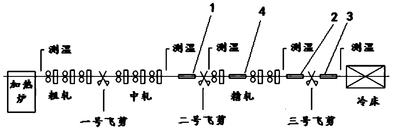
[0032] see first figure 1 , The steel bar rolling production line usually includes heating furnace, rough rolling, No. 1 flying shear, middle rolling, No. 2 flying shear, finishing rolling, No. 3 flying shear and cooling bed. According to a preferred embodiment of the present invention, the bar controlled rolling and controlled cooling system includes: the first cooling section 1, which is arranged between the outlet of the intermediate rolling group and the finishing rolling group; the inter-machine cooling section 4, which is arranged at the finishing Between the rolling mills, it shoul...


PUM


Abstract

A controlled rolling and controlled cooling system for bars comprises a first cooling section at the position of an outlet of an intermediate mill group, a machine cooling section of a finishing mill group, a second cooling section between the finishing mill group and a third flying shear, a third cooling section between the third flying shear and a cooling bed, a sensor module and a central control unit. The first cooling section, the second cooling section and the third cooling section respectively comprise one or a plurality of cooling lines arranged on a horizontal moving trolley and a bypass roll table, one cooling line or the bypass roll table can be selectively connected to a production line by horizontally moving the horizontal moving trolley, and every production line comprises one or a plurality of series connection coolers. Every cooler is connected to a water supply main pipe through one water supply branched pipe, control valves are arranged in the water supply branched pipes, and the coolers connected to the production lines are selected and used by opening and closing of the control valves. According to the controlled rolling and controlled cooling system, a plurality of cooling sections can be selected flexibly, the coolers in every cooling section can also be selectively used simultaneously, and accordingly the system not only is good in applicability, but also improves bar finished product performances.

Description

technical field [0001] The invention relates to a controlled rolling and cooling system for bars, in particular to a controlled rolling and cooling system for bars that can be flexibly configured according to requirements and can improve the performance of finished products. Background technique [0002] At present, the structure and layout of the cooler or the water penetrator of the existing bar controlled rolling and controlled cooling system are very backward, and there are two main problems: on the one hand, although it can cool the bar, the cooling effect is not ideal, and it is directly Affect the microstructure and performance of the bar, for example, the metallographic structure of the bar is not ideal, the grains are coarse and uneven, which makes it difficult to improve the performance of the finished bar, especially the qualified rate of the finished bar with high quality requirements is low, often need to add A large number of alloys are used to make up for it, ...

Claims


Application Information

Patent Timeline
Patent Type & Authority Applications(China)
IPC IPC(8): B21B45/02B21B37/74B21B38/00
Inventor 陈昕李国富陈洁董淑霞李晓滨
Owner CENT RES INST OF BUILDING & CONSTR CO LTD MCC GRP
Why Eureka
Try Eureka