
Secondary mixing type annular rotating grinding material jet flow nozzle

A secondary mixing and abrasive jet technology, applied in abrasives, spray guns, metal processing equipment, etc., can solve the problems of reducing pipeline stability, shortening service life, and poor cutting effect, and achieves improved conveying capacity, improved mixing degree, good cutting effect

Active Publication Date: 2014-02-05
WUHAN UNIV
View PDF5 Cites 12 Cited by
  • Summary
  • Abstract
  • Description
  • Claims
  • Application Information

AI Technical Summary

Problems solved by technology

In the post-mixing method, the abrasive particles need to interact with the jet many times before they can enter the interior of the jet. Most abrasives can only gather on the surface of the jet, so the mixing is not ideal. Under the same power condition, the cutting effect is not as good as that of the pre-mixing method.
However, in the pre-mixing equipment, most of the pipelines are liquid-solid mixed two-phase flow. On the one hand, the pipe wall needs to withstand the action of high-pressure water flow. On the other hand, abrasive particles form friction and extrusion on the pipe wall, which reduces the stability of the pipeline and greatly shortens the service life.

Method used


Image

  • Secondary mixing type annular rotating grinding material jet flow nozzle
  • Secondary mixing type annular rotating grinding material jet flow nozzle
  • Secondary mixing type annular rotating grinding material jet flow nozzle

Examples


Embodiment Construction

[0031] The present invention is vertically arranged when in use, and the specific implementation manner of the present invention will be further described below in conjunction with the state of the present invention in use and the accompanying drawings.

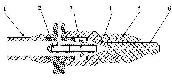
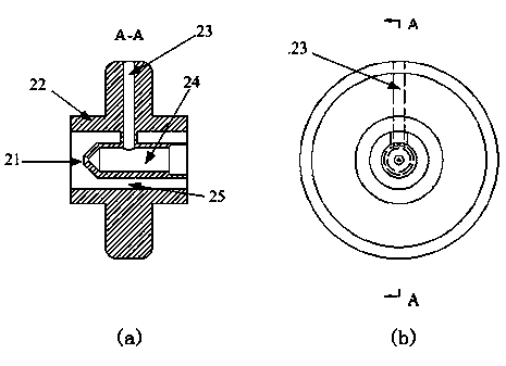
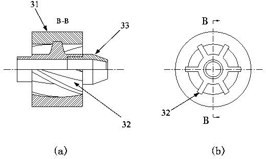
[0032] See figure 1 , this specific implementation includes a high-pressure water supply pipe 1, a primary mixing chamber 2, a flow guide device 3, a secondary mixing chamber 4, a protective cover 5 and an abrasive nozzle 6, a high-pressure water supply pipe 1, a primary mixing pipe 2, a flow guide device 3, and two The secondary mixing chamber 4 and the abrasive nozzle 6 are connected in sequence, and one end of the protective sleeve 5 is connected to the outside of the secondary mixing chamber 4 through a thread, and the other end is connected to the outside of the abrasive nozzle 6 through a thread to fix the abrasive nozzle 6 and the secondary mixing chamber 4 , can also protect the abrasive nozzle 6.

[0033] One end of...


PUM


Abstract

The invention discloses a secondary mixing type annular rotating grinding material jet flow nozzle. The secondary mixing type annular rotating grinding material jet flow nozzle comprises a high pressure water supply pipe, a primary mixing chamber, a guiding device, a secondary mixing chamber and a grinding material nozzle which are successively communicated, wherein the guiding device comprises a guiding blade fixing ring, a mixed slurry transporting pipeline and guiding blades which are distributed along the outer surface of the mixed slurry transporting pipeline; the inner wall of the guiding blade fixing ring is provided with a groove which is meshed with the guiding blades, the mixed slurry transporting pipeline and the guiding blades are located in the guiding blade fixing ring, and the two ends of the mixed slurry transporting pipeline are respectively communicated with the primary mixing chamber and the secondary mixing chamber. The secondary mixing type annular rotating grinding material jet flow nozzle provided by the invention has the advantages that the structure is simple, the cost is low, the abrasion of the inner wall of equipment is small, the mixing degree of the grinding material and a working fluid can be greatly improved, the cutting effect is good, the stability is strong, the secondary mixing type annular rotating grinding material jet flow nozzle is suitable for working fluids of various working pressures, and the secondary mixing type annular rotating grinding material jet flow nozzle is suitable for popularizing and using in a large scale.

Description

technical field [0001] The invention belongs to the technical field of high-pressure abrasive water jet cutting, and in particular relates to a secondary mixing annular rotating abrasive jet nozzle. Background technique [0002] High-pressure abrasive water jet cutting (abrasive water jet) refers to the injection of abrasives into the high-pressure working fluid during the water jet process to form a high-speed jet of liquid-solid two-phase flow to cut the target. Its main feature is that there is no thermal deformation and no residual thermal stress during the cutting process, and it can cut various materials precisely, and because the jet is attached with abrasives, it can effectively reduce the cutting threshold pressure and greatly improve the cutting efficiency. [0003] The mixing method of working fluid and abrasive can divide high-pressure abrasive waterjet into pre-mixing type and post-mixing type. Pre-mixing abrasive water jet means that part of the high-pressure ...

Claims


Application Information

Patent Timeline
IPC IPC(8): B24C5/04
Inventor 龙新平肖龙洲
Owner WUHAN UNIV
Learn More